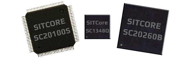
System on Chip
TinyCLR on a bare chipset. Drop a SITCore SoC onto your own PCB and you get the full TinyCLR runtime, Visual Studio step-debugging over USB, and the complete .NET feature set — at the smallest footprint and lowest unit cost.
Overview
SITCore SoCs are the lowest-cost path to add .NET computing power to a custom embedded product. The lineup spans two families:
- SC13xxx — Cortex-M4 at 80 MHz, 48-pin QFN. The compact, low-power option.
- SC20xxx — Cortex-M7 at 480 MHz, 100-pin LQFP or 265-ball BGA. Full peripheral set, on-chip Ethernet, hardware graphics.
All SoCs run the same TinyCLR firmware — your C# application code is portable across the family.
SC20xxx features
- Low-power modes with three independently controllable power domains
- RTC
- Watchdog
- Threading
- TCP/IP with SSL
- Full .NET socket interface
- Ethernet
- PPP
- Graphics
- Images
- Fonts
- Controls
- File System
- Full .NET file interface
- SD cards
- USB drives
- Native extensions
- Runtime Loadable Procedures
- Device register access
- Signal controls
- Generation
- Capture
- Pulse measurement
SC13xxx features
The SC13xxx covers the core TinyCLR feature set: threading, memory management, security (secure assemblies, secure storage, a subset of crypto libraries), and all pin-level peripherals — PWM, ADC, signal generators, SPI, UART, CAN, I²C. USB Client is supported with WebUSB and WinUSB.
Some features common to the larger SC20xxx are not native on SC13xxx, but library alternatives are available:
- Graphics — no native support, but the BasicGraphics library provides an alternative. The SC13048Q development board includes a color TFT SPI display.
- File system — no native support, but the ManagedFileSystem library is a full FAT implementation that supports file and directory access on SD cards over SPI.
- Networking — SC20xxx remains the proper way to access networks securely. As an alternative, the Wiznet W5500 Ethernet chipset and ESP32 WiFi module can be used with SC13xxx.
Specifications
| Spec | SC13048Q | SC20100S/B | SC20260B |
|---|---|---|---|
| Core | ARM Cortex-M4 32-bit | ARM Cortex-M7 32-bit | ARM Cortex-M7 32-bit |
| Speed | 80 MHz | 480 MHz | 480 MHz |
| Math co-processor | Single-precision | Double-precision | Double-precision |
| Internal RAM | 160K | 1 MByte | 1 MByte |
| User RAM | 128K | 512K | 512K + 32 MB optional external |
| Internal flash | 512K | 2 MByte | 2 MByte |
| User flash | 220K + 8 MB optional external | 640K + 8 MB optional external | 640K + 8 MB optional external |
| Instruction cache | None | 16 KByte | 16 KByte |
| Data cache | None | 16 KByte | 16 KByte |
| Package | 48-QFN 7×7 mm | S: LQFP100 14×14 mm | 265-TFBGA 14×14 mm |
| B: 100-TFBGA 8×8 mm | |||
| Temperature range | −40°C to +85°C | −40°C to +85°C | −40°C to +85°C |
Resources are shared between your application and the operating system.
Peripherals
| Peripheral | SC13048Q | SC20100S/B | SC20260B |
|---|---|---|---|
| GPIO | 37 | 74 | 163 |
| SPI | 2 | 3 | 3 |
| I²C | 2 | 2 | 3 |
| UART | 4 (2 with handshaking) | 8 (4 with handshaking) | 8 (4 with handshaking) |
| CAN | 1 | 2 | 2 |
| PWM | 10 | 16 | 29 |
| ADC | 10 | 12 | 21 |
| DAC | 1 | 2 | 2 |
| SD/SDIO/MMC | 0 | 1 | 1 |
| Quad SPI | 1 | 1 | 1 |
| USB host | 0 | 1 | 1 |
| USB client | 1 | 1 | 1 |
| Ethernet | 0 | 1 | 1 |
| LCD TFT | 0 | 0 | 1 |
| Graphics | BasicGraphics via SPI | Full Graphics via SPI | 16BPP TFT |
| Camera | 0 | 0 | 1 |
Many pins share peripherals — not all peripherals will be available simultaneously.
Power consumption
SC20xxx
| 480 MHz | 240 MHz | |
|---|---|---|
| Running | 205 mA | 110 mA |
| Idle | 170 mA | 97 mA |
| Sleep | 6.5 mA | 6.5 mA |
| Shutdown | 40 µA | 40 µA |
SC13xxx
| 80 MHz | 40 MHz | |
|---|---|---|
| Running | 12.6 mA | 7.5 mA |
| Idle | 6.2 mA | 4.2 mA |
| Sleep | 1.4 mA | 1.4 mA |
| Shutdown | 23 µA | 23 µA |
See the Power Management feature page for details.
Operational voltage
| Voltage range | |
|---|---|
| SC13xxx | 1.71V – 3.6V |
| SC20xxx | 1.62V – 3.6V |
SITCore modules (SoMs) may include other components — QSPI flash, SDRAM — that require higher voltages. Account for those when designing the supply.
Interrupts (IRQs)
The microcontrollers used in the SITCore line do not support concurrent interrupts on the same pin number, even across different ports. (The port is denoted by the second letter of the GPIO pin name — PA1 is pin 1 on port A.)
In practice: interrupts are available on up to 16 distinct pin numbers at a time. PA1 and PB1 cannot both be interrupt pins simultaneously; PA1 and PB2 can. PA1 and PA2 can also be used with interrupts at the same time.
Pinouts
GPIO pins are rated for 20 mA per pin, 140 mA total across all pins, and are 5V-tolerant.
SC13048Q
SC20100S/B
SC20260B
Getting started
The SITCore SoC runs TinyCLR — same C# code, same Visual Studio workflow as every SITCore product.
- Wire the SoC into your custom PCB — see Design considerations below for required pins, footprints, and power supply notes.
- Install Visual Studio (Community Edition works) and the TinyCLR tooling.
- Load the firmware on the SoC.
- Deploy your first application from Visual Studio.
See Getting Started for the full walkthrough — Visual Studio setup, firmware loading via the bootloader, and first deployment.
Design considerations
Footprints
SC13048Q
SC20100S
SC20100B
SC20260B

Required pins
Expose the following pins in every design to enable device programming, updates, and recovery:
- RESET
- LDR
- APP
- MOD (selects the debug interface)
- Desired debug interface(s) — see below
For more on these and other important pins, see Special Pins.
Debug interface
All SITCore products provide two debug and deployment interfaces: USB and serial. The MOD pin selects which is active at startup — MOD high selects USB; MOD low selects serial.
In serial mode, all SITCore products use UART1 except the SC20260B (chipset or board), which uses UART5.
Power supply
A clean digital power source is required. Voltages should be regulated within 10% of the specified voltage. Place 0.1 µF decoupling capacitors near every power pin. Add a larger 47 µF capacitor near the SoC if the power supply is more than a few inches away.
Analog considerations
Provide a separate filtered supply line for the Vdda and Vref+ pins. On the 260-pin devices, also provide a separate filtered ground connection for the Vssa and Vref- pins. This is not required for ADC operation, but it reduces analog supply noise and improves ADC accuracy.
Crystals
There's a lot to consider when selecting a crystal — especially the RTC crystal. Consult AN2867 from STMicroelectronics for details.
Main crystal
Most 8 MHz quartz crystals and ceramic resonators will work with SITCore SoCs. The table below shows what to look for based on the crystal's maximum equivalent series resistance (ESR), shunt capacitance (C0), and load capacitance (CL). Keep the total of C0 + CL well below the recommended maximum for stable oscillator operation.
The SC13048 SoC main clock can also operate on an internal oscillator with no external crystal — even when using USB. If the application requires better accuracy (for example, when running CAN), an external oscillator can be added.
| Max crystal ESR (Ω) | Recommended max total of C0 + CL (pF) |
|---|---|
| 40 | 49 |
| 50 | 44 |
| 60 | 40 |
| 70 | 37 |
| 80 | 35 |
| 100 | 31 |
| 200 | 22 |
| 300 | 18 |
RTC crystal
Selecting the right RTC crystal is tricky because the RTC oscillator runs at extremely low power. For reliable operation, total C0 + CL must be less than the recommended maximum.
The SC13048 SoC built-in RTC can also operate on an internal oscillator when no 32.768 kHz crystal is present. An external crystal gives better RTC accuracy.
| Max crystal ESR (kΩ) | Recommended max total of C0 + CL (pF) |
|---|---|
| 30 | 9.9 |
| 40 | 8.5 |
| 50 | 7.6 |
| 60 | 7.0 |
| 70 | 6.5 |
| 80 | 6.0 |
| 90 | 5.7 |
| 100 | 5.4 |
When laying out the board, keep the crystal as close to the SoC as possible. Surround the oscillator circuit with a grounded guard ring or ground plane on the same layer to reduce noise.
RTC power
The VBAT pin can optionally power the RTC when the system's main power is off. SITCore chipsets and modules include a built-in charging circuit that can be enabled to charge an external supercap. See the Real-Time Clock feature page for details.
QuadSPI external flash
SITCore supports 16 MByte external QuadSPI flash chips. Tested options:
| Manufacturer | Part number |
|---|---|
| Winbond Electronics | W25Q128JVSIM |
| Winbond Electronics | W25Q128JVSIQ |
Reset
SITCore processors have a permanent internal pull-up resistor on the RESET (NRST) pin. No external pull-up is required.
Oven reflow profile
SITCore SoCs are not sealed for moisture. Bake SoCs before reflow — required in humid environments. Reflow can damage the SoC if temperature is too high or exposure too long.
GHI Electronics uses lead-free reflow profiles based on AIM SAC 305 solder (3% silver, 0.5% copper). The thermal mass of the assembled board and the sensitivity of its components affect total dwell time. The two profiles below differ in peak temperature and time above liquids (TAL): the shorter applies to smaller assemblies; the longer applies to larger ones (back-planes, high-density boards). The shaded area shows the process window. These are starting points — your oven and assembly determine the final process.
Ordering
| Part number | Description | MSRP |
|---|---|---|
| SC-13048Q-A | SITCore SC13048Q SoC | $15.95 @100 |
| SC-20100S-A | SITCore SC20100S SoC | $25.95 @100 |
| SC-20100B-A | SITCore SC20100B SoC | Special order — contact us |
| SC-20260B-A | SITCore SC20260B SoC | Special order — contact us |
All SITCore chipsets are available through our global distributors.
See also
If you don't need a fully custom PCB, these SITCore products are built around the same chipsets and run the same TinyCLR firmware:
- System on Module — pre-validated modules with memory, networking, and chipset in one package. Drop onto your own carrier board.
- Single Board Computer — maker-friendly form factors (Arduino, Pico, Feather, micro:bit). Plug in USB and code.
- Development Board — ready-to-go evaluation hardware with display, peripherals, and debug headers.