Servo Motor

So far PWM has dimmed a light and made a sound. Now it moves something. A servo motor turns its arm to an exact angle, and holds it there, based on the width of the pulses you send it. By the end of this lesson you'll sweep the arm back and forth, and stop it mid-sweep with a breakpoint.
About 35 minutes.
What you'll learn
- How a servo reads its position from pulse width
- How to convert an angle into a duty cycle
- How to calibrate a servo to its real range
- Why a motor gets its power from 5V, not from a signal pin
What you'll need
- From the kit:
- Positional servo motor, with a plastic arm (horn) attached
- Jumper wires
- The Sound buzzer can stay in place
Pin reference
| Servo wire | FEZ Flea | FEZ Bit |
|---|---|---|
| Orange (signal) | PA1 (PWM controller 2) | P14 (PWM controller 13) |
| Red (power) | 5V | 5V (adapter) |
| Brown (ground) | GND | GND |
A servo needs a steady 50 Hz, so it gets a controller no other part changes:
- FEZ Flea
- FEZ Bit
PA1 shares controller 2 with PA5, the blue channel from RGB LEDs. Both use the same frequency when nothing else changes it, but to keep things simple, remove the RGB module for this lesson. The buzzer on PB8 has a controller to itself and can stay.
P14 is the only channel on controller 13, so nothing else is affected. The RGB module and the buzzer can stay wired.
Step 1 — Create the project
Create a new TinyCLR Application project and install the GHIElectronics.TinyCLR.Devices.Pwm and GHIElectronics.TinyCLR.Pins NuGet packages.
Need the steps? Start Here covers creating a project and deploying.
Step 2 — Wire the servo

The servo ends in a 3-hole socket. Push a pin-to-pin jumper wire into each hole, then plug the other ends into three empty breadboard rows.
With USB unplugged:
- FEZ Flea
- FEZ Bit
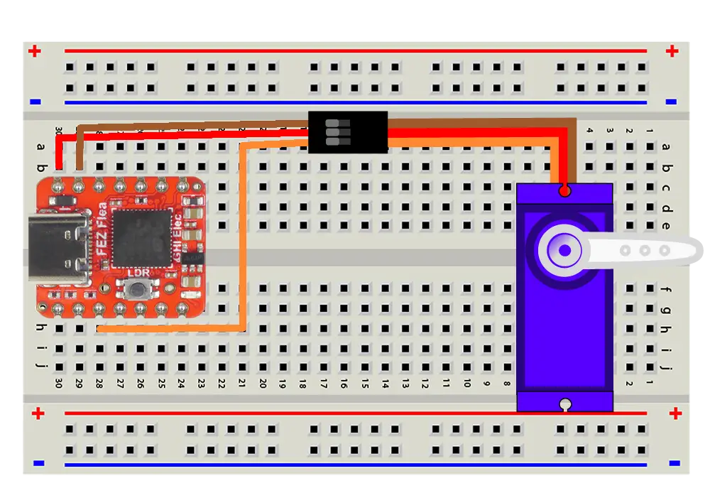
- Connect the orange (signal) to PA1.
- Connect the red (power) to the Flea's 5V pin.
- Connect the brown (ground) to the Flea's GND pin.
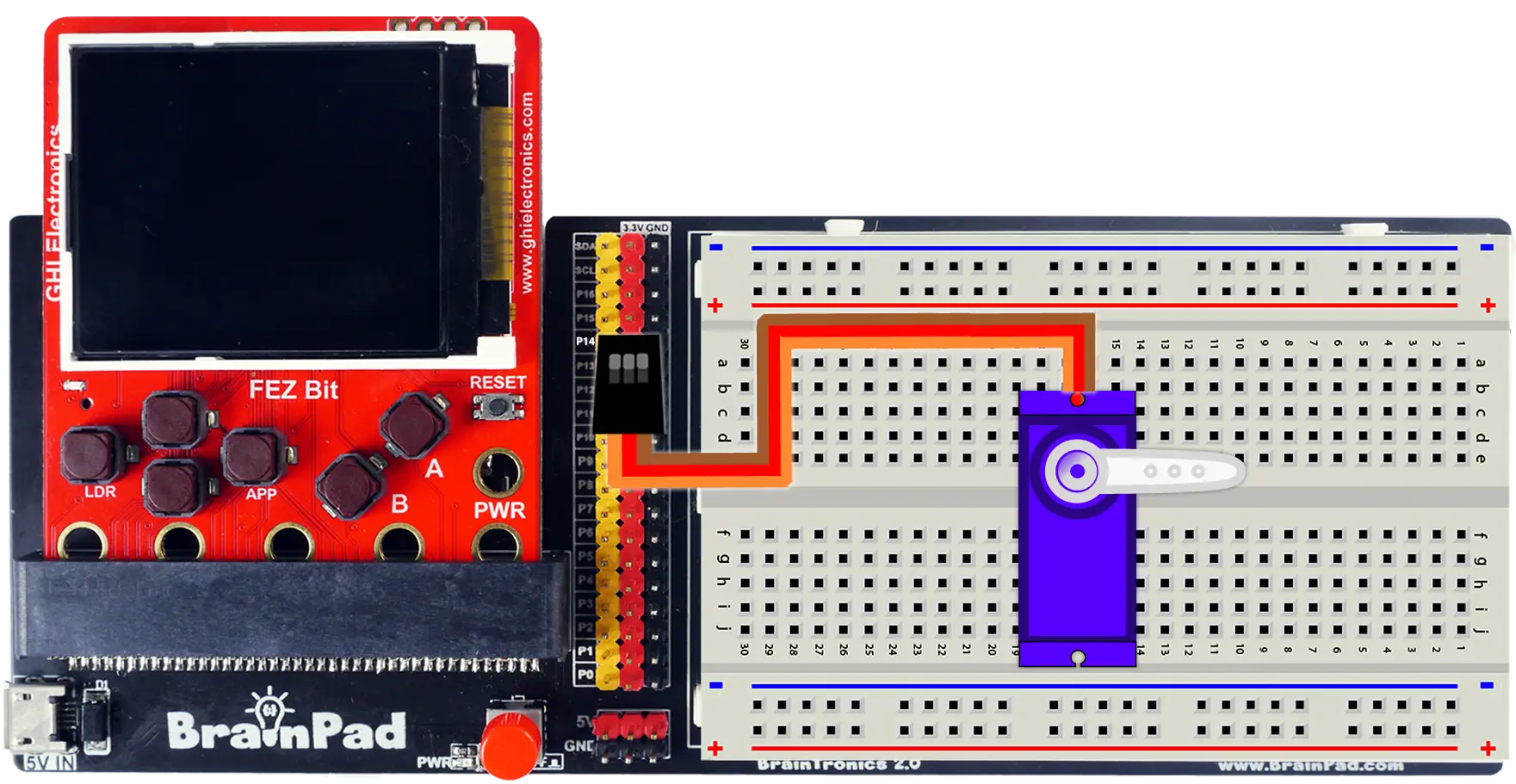
In projects that have more components requiring power we can use the + and - rails to send power to all the components.
- For this exercise we can just plug directly into the P14 pin header. Align the orange and yellow header pin, this will align the power and ground pins too.
Connect the red wire to a power pin, never to a signal pin. A servo's motor draws far more current than a pin can provide. The signal wire only carries the pulses.
Servos work best at 5V. 3.3V is fine for bench testing like this lesson, where nothing is attached to the arm — expect less torque, and a servo that may stutter or stall as soon as it has real work to do. Give it 5V for anything that has to push, lift, or turn a load.
Step 3 — Center the servo
A servo expects a pulse every 20 ms (50 Hz). The width of that pulse sets the angle, and 1.5 ms is the center. As a duty cycle, that's 1.5 ÷ 20 = 0.075.
- FEZ Flea
- FEZ Bit
using System.Device.Pwm;
using System.Threading;
using GHIElectronics.TinyCLR.Pins;

using PwmChannel servo = PwmChannel.Create(
    FEZFlea.Timer.Pwm.Controller2.Chip,
    FEZFlea.Timer.Pwm.Controller2.PA1,
    50,       // 50 Hz: one pulse every 20 ms
    0.075);   // 1.5 ms pulse: center

servo.Start();

Thread.Sleep(Timeout.Infinite);
using System.Device.Pwm;
using System.Threading;
using GHIElectronics.TinyCLR.Pins;

using PwmChannel servo = PwmChannel.Create(
    FEZBit.Timer.Pwm.Controller13.Chip,
    FEZBit.Timer.Pwm.Controller13.P14,
    50,       // 50 Hz: one pulse every 20 ms
    0.075);   // 1.5 ms pulse: center

servo.Start();

Thread.Sleep(Timeout.Infinite);
Press F5. The servo turns to its center position and stops. Try turning the arm gently with your fingers: it pushes back. The servo keeps holding the angle for as long as the pulses keep coming.
Once it's centered, pull the arm off and push it back on pointing straight up. Now it's easy to see which way it moves.
Step 4 — Move to an angle
Duty cycles like 0.075 aren't a natural way to think about a motor. A small method converts degrees into a duty cycle:
- FEZ Flea
- FEZ Bit
using System.Device.Pwm;
using System.Threading;
using GHIElectronics.TinyCLR.Pins;

using PwmChannel servo = PwmChannel.Create(
    FEZFlea.Timer.Pwm.Controller2.Chip,
    FEZFlea.Timer.Pwm.Controller2.PA1,
    50,
    0.075);

servo.Start();

// Pulse widths in milliseconds for 0° and 180°.
const double MinPulse = 1.0;
const double MaxPulse = 2.0;
const double Period = 20.0;     // 50 Hz

while (true) {
    SetAngle(0);
    Thread.Sleep(1000);

    SetAngle(90);
    Thread.Sleep(1000);

    SetAngle(180);
    Thread.Sleep(1000);

    SetAngle(90);
    Thread.Sleep(1000);
}

void SetAngle(double degrees) {
    double pulse = MinPulse + (MaxPulse - MinPulse) * degrees / 180;
    servo.DutyCycle = pulse / Period;
}
using System.Device.Pwm;
using System.Threading;
using GHIElectronics.TinyCLR.Pins;

using PwmChannel servo = PwmChannel.Create(
    FEZBit.Timer.Pwm.Controller13.Chip,
    FEZBit.Timer.Pwm.Controller13.P14,
    50,
    0.075);

servo.Start();

// Pulse widths in milliseconds for 0° and 180°.
const double MinPulse = 1.0;
const double MaxPulse = 2.0;
const double Period = 20.0;     // 50 Hz

while (true) {
    SetAngle(0);
    Thread.Sleep(1000);

    SetAngle(90);
    Thread.Sleep(1000);

    SetAngle(180);
    Thread.Sleep(1000);

    SetAngle(90);
    Thread.Sleep(1000);
}

void SetAngle(double degrees) {
    double pulse = MinPulse + (MaxPulse - MinPulse) * degrees / 180;
    servo.DutyCycle = pulse / Period;
}
Press F5. The arm swings between three positions, one second at each.
SetAnglemaps 0°–180° onto a pulse betweenMinPulseandMaxPulse, then divides by the 20 ms period to get the duty cycle.- Each move takes time. The servo turns fast, but not instantly: that's what the one-second pause allows for.
Look closely at the angles. Chances are the arm moves less than a full half-turn from 0° to 180°. That's the next step.
Step 5 — Calibrate the range
1 ms to 2 ms is the textbook range, but many servos, including small hobby servos like the one in the kit, turn further with a wider range, often 0.5 ms to 2.5 ms. Every model is a little different, so find your own:
- Change
MinPulseto0.5andMaxPulseto2.5, and press F5. - Watch the arm at 0° and 180°. It should now travel close to a full half-turn.
- Listen at each end. If the servo buzzes or strains while holding still, it's pushing against its internal stop. Nudge that value back toward the center (for example
0.6or2.4) until it goes quiet.
Don't leave a servo straining against its end stop. It draws high current, heats up, and can strip its plastic gears.
Try the debugger: set a breakpoint on servo.DutyCycle = pulse / Period;, press F5, and hover over pulse each time it stops. You can see the exact pulse width behind each angle, and adjust your constants to match.
Step 6 — Sweep, and stop it with a breakpoint
Replace the while loop with a smooth sweep, one degree at a time:
while (true) {
    for (int angle = 0; angle <= 180; angle++) {
        SetAngle(angle);
        Thread.Sleep(10);
    }

    for (int angle = 180; angle >= 0; angle--) {
        SetAngle(angle);
        Thread.Sleep(10);
    }
}
Press F5. The arm sweeps back and forth smoothly, about two seconds each way. Change the Thread.Sleep to make it faster or slower.
Now stop it mid-sweep:
- While it's moving, set a breakpoint on
SetAngle(angle);in the first loop. - The arm stops right where it was and holds that position. Hover over
angleand compare it with the arm. - Press F5 a few times. Each press moves the arm exactly one degree.
- Remove the breakpoint and press F5. The sweep carries on.
The breakpoint doesn't pause a simulation. It pauses the motor.
How it works
Pulse width is position
A servo has three parts inside: a small DC motor, a gearbox, and a potentiometer attached to the output shaft that measures its angle. A control chip compares that measured angle with the one requested by the pulse width, and drives the motor until they match.
0°     ▇▇▁▁▁▁▁▁▁▁▁▁▁▁▁▁▁▁▁▁▁▁▁▁▁▁▁▁▁▁▁▁▁▁▁▁▁▁▁▁▇▇▁▁▁▁   1.0 ms high
90°    ▇▇▇▁▁▁▁▁▁▁▁▁▁▁▁▁▁▁▁▁▁▁▁▁▁▁▁▁▁▁▁▁▁▁▁▁▁▁▁▁▇▇▇▁▁▁   1.5 ms high
180°   ▇▇▇▇▁▁▁▁▁▁▁▁▁▁▁▁▁▁▁▁▁▁▁▁▁▁▁▁▁▁▁▁▁▁▁▁▁▁▁▁▇▇▇▇▁▁   2.0 ms high
       |←──────────────── 20 ms ───────────────→|
       (each block = 0.5 ms)
Unlike an LED, a servo doesn't care about average power. It measures the width of each high pulse. The gap after it just needs to be about the same every time, and that's why the frequency must stay at a steady 50 Hz.
That's also why a servo holds its position under a breakpoint: the pulses come from the chip's timer, so they keep arriving while your code is paused.
Why the servo needs 5V
The pin only sends a signal, which takes almost no current. The motor is a different story: a small servo can draw several hundred milliamps while moving, and more if it stalls. That power comes from a supply pin, not a signal pin.
5V or 3.3V? A hobby servo is designed for 5V and delivers its rated torque there. At 3.3V it still turns, just with less force — fine for an unloaded arm on the bench, unreliable the moment it has to move something. Wire it to 5V once your project does real work:
- FEZ Flea: the 5V pin comes straight from the USB cable.
- FEZ Bit: the adapter board's 5V comes from its micro USB cable.
If your board resets or disconnects from Visual Studio whenever the servo moves, the USB port can't keep up with the motor. Try a different USB port, or a powered USB hub.
Positional vs. continuous rotation
The kit's servo is positional: it turns to an angle, usually within a half-turn. Continuous-rotation servos look identical, but the pulse width sets speed and direction instead: 1.5 ms stops, shorter spins one way, longer spins the other. Same wiring, same code, different meaning.
For a ready-made servo class, see Servo motors on the PWM page.
Try this
- Slow motion. Make the sweep take 10 seconds each way, without changing the step size.
- Button control. Wire two buttons from Digital Input: each press moves the arm 15° left or right. Don't go past 0° or 180°.
- Clock hand. Turn the servo into a seconds hand: move from 0° to 180° over 60 seconds, then snap back to the start and beep with the buzzer from Sound.
- Gauge. Draw a scale from 0 to 10 on a piece of paper behind the arm. Write a
ShowValue(int value)method that points the arm at the right number.
The distance sensor lesson returns to the servo: mount the sensor on the arm and you're sweeping the room like a radar.
Next
Analog Input: read a knob with the ADC, and watch its value change live in the debugger as you turn it.
Something not working, or a step unclear? Ask in the TinyCLR forum — we read every post.