RGB LEDs

An RGB LED is three LEDs — red, green, and blue — in one package. Turn them on in combinations and you get seven colors. Dim each one with PWM and you get practically any color at all.
Along the way you'll run an experiment that reveals how PWM really works inside the chip: several pins can share one controller, and that controller has just one frequency.
About 40 minutes.
What you'll learn
- How red, green, and blue light mix into other colors
- How to drive a color pattern from arrays
- How to mix any color with three PWM channels
- Why channels on the same PWM controller always share a frequency — but each keeps its own duty cycle
What you'll need
- From the kit:
- Color (RGB) LED module
- Jumper wires
- The LED from Digital Output can come out — the RGB module replaces it
Pin reference
| RGB module pin | FEZ Flea | FEZ Bit |
|---|---|---|
| R (red) | PA3 — PWM controller 15 | P0 — PWM controller 3 |
| G (green) | PA2 — PWM controller 15 | P1 — PWM controller 3 |
| B (blue) | PA5 — PWM controller 2 | P3 — PWM controller 3 |
| GND | GND | GND |
Keep an eye on the controller numbers — they matter in Step 5.
Step 1 — Create the project
Create a new TinyCLR Application project and install the GHIElectronics.TinyCLR.Devices.Gpio, GHIElectronics.TinyCLR.Devices.Pwm, and GHIElectronics.TinyCLR.Pins NuGet packages.
Need the steps? Start Here covers creating a project and deploying.
Step 2 — Wire the RGB LED
The module has the three current-limiting resistors built in, so its color pins connect straight to your board. The three LEDs inside share one cathode, which is the module's GND pin — so each color turns on by driving its pin high.
With USB unplugged:
- FEZ Flea
- FEZ Bit
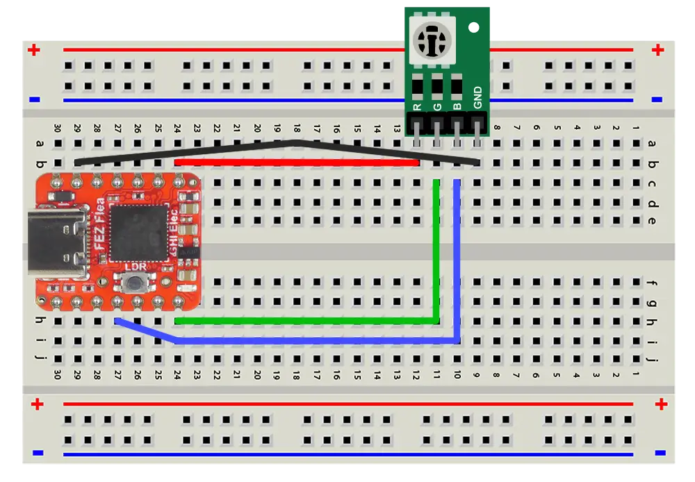
- Remove the LED and resistor from Digital Output.
- Plug the RGB module into the breadboard, each pin in its own row.
- With pin-to-pin jumper wires, connect R to PA3, G to PA2, B to PA5, and GND to the − rail (or a GND pin).
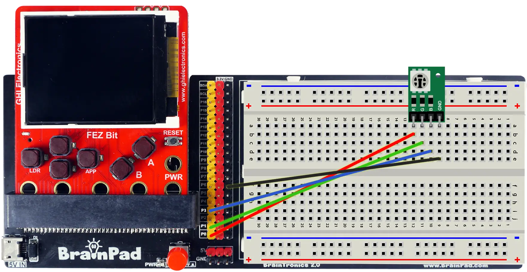
- Remove the LED and resistor from Digital Output.
- Plug the RGB module into the breadboard, each pin in its own row.
- With pin-to-socket jumper wires from the adapter's header, connect P0 to R, P1 to G, P3 to B, and GND to the module's GND row.
Step 3 — Mix colors with digital outputs
Start with plain on and off. With three LEDs, that's 2 × 2 × 2 = 8 combinations: off, plus seven colors. This program cycles through them, using arrays to describe the pattern:
- FEZ Flea
- FEZ Bit
using System.Device.Gpio;
using System.Diagnostics;
using System.Threading;
using GHIElectronics.TinyCLR.Pins;

using GpioController controller = new GpioController();

int redPin = FEZFlea.GpioPin.PA3;
int greenPin = FEZFlea.GpioPin.PA2;
int bluePin = FEZFlea.GpioPin.PA5;

controller.OpenPin(redPin, PinMode.Output);
controller.OpenPin(greenPin, PinMode.Output);
controller.OpenPin(bluePin, PinMode.Output);

// One column per color: is red, green, blue on?
string[] names = { "Red",  "Green", "Blue", "Yellow", "Cyan", "Magenta", "White" };
bool[] red     = { true,   false,   false,  true,     false,  true,      true    };
bool[] green   = { false,  true,    false,  true,     true,   false,     true    };
bool[] blue    = { false,  false,   true,   false,    true,   true,      true    };

while (true) {
    for (int i = 0; i < names.Length; i++) {
        SetColor(red[i], green[i], blue[i]);
        Debug.WriteLine(names[i]);
        Thread.Sleep(1000);
    }
}

void SetColor(bool r, bool g, bool b) {
    controller.Write(redPin, r ? PinValue.High : PinValue.Low);
    controller.Write(greenPin, g ? PinValue.High : PinValue.Low);
    controller.Write(bluePin, b ? PinValue.High : PinValue.Low);
}
using System.Device.Gpio;
using System.Diagnostics;
using System.Threading;
using GHIElectronics.TinyCLR.Pins;

using GpioController controller = new GpioController();

int redPin = FEZBit.GpioPin.P0;
int greenPin = FEZBit.GpioPin.P1;
int bluePin = FEZBit.GpioPin.P3;

controller.OpenPin(redPin, PinMode.Output);
controller.OpenPin(greenPin, PinMode.Output);
controller.OpenPin(bluePin, PinMode.Output);

// One column per color: is red, green, blue on?
string[] names = { "Red",  "Green", "Blue", "Yellow", "Cyan", "Magenta", "White" };
bool[] red     = { true,   false,   false,  true,     false,  true,      true    };
bool[] green   = { false,  true,    false,  true,     true,   false,     true    };
bool[] blue    = { false,  false,   true,   false,    true,   true,      true    };

while (true) {
    for (int i = 0; i < names.Length; i++) {
        SetColor(red[i], green[i], blue[i]);
        Debug.WriteLine(names[i]);
        Thread.Sleep(1000);
    }
}

void SetColor(bool r, bool g, bool b) {
    controller.Write(redPin, r ? PinValue.High : PinValue.Low);
    controller.Write(greenPin, g ? PinValue.High : PinValue.Low);
    controller.Write(bluePin, b ? PinValue.High : PinValue.Low);
}
Press F5. The LED cycles through seven colors, and the Output window names each one.
- The arrays line up in columns — reading down column
igives the name and the three on/off values for one color. Add a column to all four arrays and the pattern grows. - Yellow is red + green, cyan is green + blue, magenta is red + blue, and all three together make white.
Try the debugger: set a breakpoint on Thread.Sleep(1000);. Each time it stops, hover over i and compare the LED with that column of the arrays.
If a color looks wrong, check it against the arrays: a missing color usually means one wire in the wrong row, and a color that's always on usually means a wire on the wrong pin.
Step 4 — Mix any color with PWM
Seven colors is a start — but each LED only has two settings. With PWM from Breathing LED, each one gets a full range of brightness, and the mix can land anywhere in between. This program fades smoothly around the color wheel: red → green → blue → red.
- FEZ Flea
- FEZ Bit
using System.Device.Pwm;
using System.Threading;
using GHIElectronics.TinyCLR.Pins;

using PwmChannel red = PwmChannel.Create(
    FEZFlea.Timer.Pwm.Controller15.Chip, FEZFlea.Timer.Pwm.Controller15.PA3, 1000, 0);
using PwmChannel green = PwmChannel.Create(
    FEZFlea.Timer.Pwm.Controller15.Chip, FEZFlea.Timer.Pwm.Controller15.PA2, 1000, 0);
using PwmChannel blue = PwmChannel.Create(
    FEZFlea.Timer.Pwm.Controller2.Chip, FEZFlea.Timer.Pwm.Controller2.PA5, 1000, 0);

red.Start();
green.Start();
blue.Start();

while (true) {
    for (int step = 0; step <= 100; step++) {
        double t = step / 100.0;
        SetColor(1 - t, t, 0);          // red → green
        Thread.Sleep(20);
    }
    for (int step = 0; step <= 100; step++) {
        double t = step / 100.0;
        SetColor(0, 1 - t, t);          // green → blue
        Thread.Sleep(20);
    }
    for (int step = 0; step <= 100; step++) {
        double t = step / 100.0;
        SetColor(t, 0, 1 - t);          // blue → red
        Thread.Sleep(20);
    }
}

// Each color from 0.0 (off) to 1.0 (full), with the brightness curve from Breathing LED.
void SetColor(double r, double g, double b) {
    red.DutyCycle = r * r;
    green.DutyCycle = g * g;
    blue.DutyCycle = b * b;
}
using System.Device.Pwm;
using System.Threading;
using GHIElectronics.TinyCLR.Pins;

using PwmChannel red = PwmChannel.Create(
    FEZBit.Timer.Pwm.Controller3.Chip, FEZBit.Timer.Pwm.Controller3.P0, 1000, 0);
using PwmChannel green = PwmChannel.Create(
    FEZBit.Timer.Pwm.Controller3.Chip, FEZBit.Timer.Pwm.Controller3.P1, 1000, 0);
using PwmChannel blue = PwmChannel.Create(
    FEZBit.Timer.Pwm.Controller3.Chip, FEZBit.Timer.Pwm.Controller3.P3, 1000, 0);

red.Start();
green.Start();
blue.Start();

while (true) {
    for (int step = 0; step <= 100; step++) {
        double t = step / 100.0;
        SetColor(1 - t, t, 0);          // red → green
        Thread.Sleep(20);
    }
    for (int step = 0; step <= 100; step++) {
        double t = step / 100.0;
        SetColor(0, 1 - t, t);          // green → blue
        Thread.Sleep(20);
    }
    for (int step = 0; step <= 100; step++) {
        double t = step / 100.0;
        SetColor(t, 0, 1 - t);          // blue → red
        Thread.Sleep(20);
    }
}

// Each color from 0.0 (off) to 1.0 (full), with the brightness curve from Breathing LED.
void SetColor(double r, double g, double b) {
    red.DutyCycle = r * r;
    green.DutyCycle = g * g;
    blue.DutyCycle = b * b;
}
Press F5. The LED glides through orange, yellow, lime, teal, purple, pink — every shade between the three primaries.
Try the debugger: set a breakpoint inside the second loop and hover over t. The color on the LED is frozen at that exact point of the fade. Move the breakpoint to another loop to stop at a different part of the wheel.
Step 5 — One controller, one frequency
Every channel in Step 4 runs at 1000 Hz. What happens if just one of them changes?
Replace the while loop in Step 4 with this — it sets all three colors to the same dim level, then slows only the green channel down to 20 Hz, the flicker speed from Breathing LED:
SetColor(0.5, 0.5, 0.5);   // all three on at the same level

Thread.Sleep(3000);        // steady for three seconds...

green.Frequency = 20;      // ...then slow down only green

Thread.Sleep(Timeout.Infinite);
Press F5 and watch the LED closely — look at the individual colors in the package, not just the mix. After three seconds, more than just green starts to flicker:
- FEZ Flea
- FEZ Bit
Red and green flicker. Blue stays steady.
Red (PA3) and green (PA2) are both channels on PWM controller 15. Blue (PA5) is on controller 2. Changing green's frequency changed controller 15's frequency — and red went along with it.
Red, green, and blue all flicker.
Red (P0), green (P1), and blue (P3) are all channels on PWM controller 3. Changing green's frequency changed controller 3's frequency — for every channel on it.
Notice what didn't change: every color still has the brightness you set. Each channel kept its own duty cycle; only the shared frequency moved.
How it works
Mixing light
Mixing light isn't like mixing paint. Paint absorbs colors, so mixing makes things darker. Light adds up, so mixing makes things brighter:
| Red | Green | Blue | You see |
|---|---|---|---|
| ● | Red | ||
| ● | Green | ||
| ● | Blue | ||
| ● | ● | Yellow | |
| ● | ● | Cyan | |
| ● | ● | Magenta | |
| ● | ● | ● | White |
With PWM, each column can be anywhere from off to full — 50% red with 100% green looks lime, 100% red with 30% green looks orange.
Controllers and channels
A PWM controller is a timer inside the chip. It counts up over and over, and each full count is one period — so the controller decides the frequency. Each channel watches the same counter and switches its pin off at its own point in the count — so each channel decides its own duty cycle.
Controller counter   0 ───────────────────────── end of period → restart
Red channel          ▇▇▇▇▇▇▇▇▇▇▇▇▇▇▁▁▁▁▁▁▁▁▁▁▁   switches off at 60%
Green channel        ▇▇▇▇▇▁▁▁▁▁▁▁▁▁▁▁▁▁▁▁▁▁▁▁▁   switches off at 20%
                     |←──────── one shared period ────────→|
That's why there's only one frequency per controller: there's only one counter. Your code can set the frequency from any channel, but it's always the controller's frequency that changes.
The pin names in the pin reference — Timer.Pwm.Controller15.PA3, Timer.Pwm.Controller3.P0 — tell you which controller every pin belongs to.
Why it matters
For LEDs, the frequency hardly matters — anything fast enough not to flicker looks the same. But some parts depend on frequency:
- A buzzer's pitch is its frequency. Play a note, and every other channel on that controller changes frequency too.
- A servo expects pulses at a specific rate — 50 Hz.
The rule: anything that needs its own frequency gets its own controller. You'll put it to work in the next lesson.
Try this
- Traffic light. Green for 5 seconds, yellow for 2, red for 5 — using the digital version from Step 3.
- Color picker. Wire the button from Digital Input and make each press step through a list of your favorite colors. Store them as three
doublearrays, one per channel. - Mood lamp. Pick a random color every few seconds, and fade smoothly from the current color to the new one.
- Breathe in color. Combine this lesson with Breathing LED: breathe in and out, shifting to a new color on every breath.
Next
Sound — change the frequency instead of the duty cycle: make a piezo buzzer beep, sweep, and play a melody — on a controller of its own.
Something not working, or a step unclear? Ask in the TinyCLR forum — we read every post.