Light and Logic

The potentiometer was a well-behaved sensor: linear, predictable, and identical for everyone. A photoresistor is none of those things. It doesn't even produce a voltage — you have to build a circuit that turns its resistance into one.
This lesson is about the gap between a reading and a decision. You'll build a night-light that switches an LED on when the room gets dark — and then fix the flicker that every first attempt has.
About 40 minutes.
What you'll learn
- How to build your own voltage divider so a resistance can be read by the ADC
- Why a sensor reading means nothing until you calibrate it to your own room
- How to turn a number into a decision with a threshold
- Why a single threshold flickers, and how hysteresis fixes it
What you'll need
- From the kit:
- Light sensor (photoresistor)
- 1× 27 kΩ resistor — marked
27Kon the paper strip - 1× LED and 1× 220 Ω resistor — marked
220R - Jumper wires
First time with these parts?
- LED — the longer leg is the positive side (anode) and goes toward the pin; the shorter leg, next to the flat edge of the rim, goes toward GND. In backwards it just stays dark, so nothing is harmed.
- Resistor — no polarity, so either way round works. The kit's resistors have five bands, while most charts online show four: 220 Ω is red · red · black · black · brown, and 27 kΩ is red · violet · black · red · brown.
220Ron the paper strip means 220 Ω — the letter sits where the decimal point would go.27Kis 27 kΩ.
More in Start Here → Parts you'll meet first.
Pin reference
| Connection | FEZ Flea | FEZ Bit |
|---|---|---|
| Divider output (signal) | PA4 — ADC controller 1 | P10 — ADC controller 1 |
| Photoresistor to | 3V3 | 3.3V (adapter) |
| 27 kΩ resistor to | GND | GND |
| LED (through the 220 Ω resistor) | PA3 | P0 |
Step 1 — Create the project
Create a new TinyCLR Application project and install GHIElectronics.TinyCLR.Devices.Adc, GHIElectronics.TinyCLR.Devices.Gpio, and GHIElectronics.TinyCLR.Pins.
Need the steps? Start Here covers creating a project and deploying.
Step 2 — Build a voltage divider
A photoresistor's resistance changes with light: a few kilohms in bright light, hundreds of kilohms in the dark. The ADC can't measure resistance — only voltage. So pair the photoresistor with a fixed resistor and read the point between them, exactly like the potentiometer's wiper in Analog Input.
3.3V ──┬──────────────┐
       │              │
  [photoresistor]     │   bright light → low resistance → more voltage here
       │              │
       ├───────────── signal ──→ ADC pin
       │              │
    [27 kΩ]           │   dark → high resistance → less voltage here
       │              │
GND ───┴──────────────┘
With USB unplugged:
- FEZ Flea
- FEZ Bit
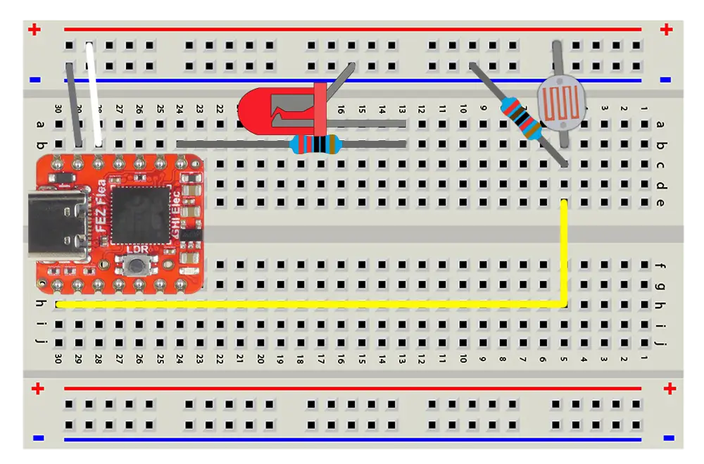
- Remove the potentiometer from the previous lesson. Leave the 3.3v and GND connected to the + and - rails, also leave the LED and its 220 Ω resistor on PA3.
- Plug the photoresistor from the + rail to an empty row. It has no polarity — either way round works.
- Plug the 27 kΩ resistor from that same row to the − rail — either way round is fine.
- Connect that row to PA4.
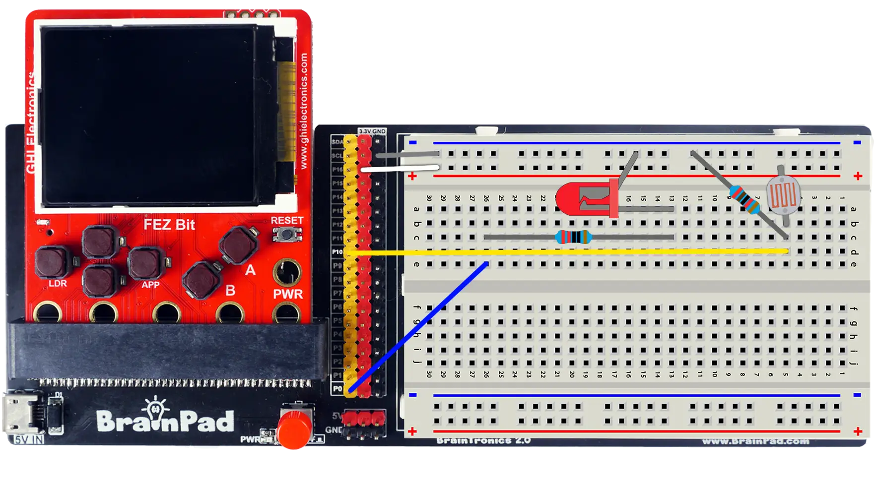
- Remove the potentiometer from the previous lesson. Leave the 3.3v and GND connected to the + and - rails, also leave the LED and its 220 Ω resistor on P0.
- Plug the photoresistor from the + rail to an empty row. It has no polarity — either way round works.
- Plug the 27 kΩ resistor from that same row to the − rail — either way round is fine.
- Connect that row to header pin P10.
The photoresistor and the 27 kΩ resistor now split 3.3 V between them, and your board reads the split point.
Step 3 — Read the light
Same ReadRatio as the knob, with the averaging helper from Analog Input — sensor readings deserve it more than knobs do:
- FEZ Flea
- FEZ Bit
using System.Diagnostics;
using System.Threading;
using GHIElectronics.TinyCLR.Devices.Adc;
using GHIElectronics.TinyCLR.Pins;

var adc = AdcController.FromName(FEZFlea.Adc.Controller1.Id);
var lightSensor = adc.OpenChannel(FEZFlea.Adc.Controller1.PA4);

while (true) {
    double light = ReadAverage(10);

    Debug.WriteLine("Light: " + light.ToString("N3"));
    Thread.Sleep(200);
}

double ReadAverage(int samples) {
    double total = 0;

    for (int i = 0; i < samples; i++) {
        total += lightSensor.ReadRatio();
    }

    return total / samples;
}
using System.Diagnostics;
using System.Threading;
using GHIElectronics.TinyCLR.Devices.Adc;
using GHIElectronics.TinyCLR.Pins;

var adc = AdcController.FromName(FEZBit.Adc.Controller1.Id);
var lightSensor = adc.OpenChannel(FEZBit.Adc.Controller1.P10);

while (true) {
    double light = ReadAverage(10);

    Debug.WriteLine("Light: " + light.ToString("N3"));
    Thread.Sleep(200);
}

double ReadAverage(int samples) {
    double total = 0;

    for (int i = 0; i < samples; i++) {
        total += lightSensor.ReadRatio();
    }

    return total / samples;
}
Press F5 and watch the Output window while you:
- Cup your hand over the sensor. The number drops.
- Shine a phone light on it. The number climbs.
- Leave it alone. It drifts slightly as clouds, screens, and people move.
Now compare with the knob in the last lesson, and notice three things:
- The range is not 0 to 1. In a normal room you might see 0.3 to 0.8 and never reach either end.
- It's not linear. Doubling the light doesn't double the reading — a photoresistor's resistance changes by ratio, not by amount.
- It's yours alone. Your numbers depend on your room, your lamp, your sensor. Nobody else's thresholds will fit.
Which is why the next step measures rather than assumes.
Step 4 — Calibrate to your room
Before deciding what "dark" means, find out what your own circuit actually reports. This program tracks the lowest and highest readings it has seen:
double darkest = 1.0;
double brightest = 0.0;

while (true) {
    double light = ReadAverage(10);

    if (light < darkest) darkest = light;
    if (light > brightest) brightest = light;

    Debug.WriteLine("Light: " + light.ToString("N3") +
                    "   darkest: " + darkest.ToString("N3") +
                    "   brightest: " + brightest.ToString("N3"));

    Thread.Sleep(200);
}
Replace the while loop with it and press F5. For about 20 seconds:
- Cover the sensor completely with your hand or a cup.
- Uncover it and let the room light land on it.
- Shine a phone light straight at it.
Write down your darkest and brightest. Halfway between them is a reasonable place to put a threshold:
threshold = (darkest + brightest) / 2
Try the debugger: instead of reading the numbers as they scroll past, set a breakpoint on Debug.WriteLine(...) and put darkest and brightest in the Watch window. Cover the sensor, press F5, and both values update at each stop.
Step 5 — The night-light (and its flicker)
Now make a decision: below the threshold, the room is dark, so light the LED.
- FEZ Flea
- FEZ Bit
using System.Device.Gpio;
using System.Diagnostics;
using System.Threading;
using GHIElectronics.TinyCLR.Devices.Adc;
using GHIElectronics.TinyCLR.Pins;

var adc = AdcController.FromName(FEZFlea.Adc.Controller1.Id);
var lightSensor = adc.OpenChannel(FEZFlea.Adc.Controller1.PA4);

using GpioController gpio = new GpioController();
int ledPin = FEZFlea.GpioPin.PA3;

gpio.OpenPin(ledPin, PinMode.Output);

// Use the number you measured in Step 4.
const double Threshold = 0.45;

while (true) {
    double light = ReadAverage(10);
    bool dark = light < Threshold;

    gpio.Write(ledPin, dark ? PinValue.High : PinValue.Low);
    Debug.WriteLine("Light: " + light.ToString("N3") + (dark ? "   DARK" : ""));

    Thread.Sleep(100);
}

double ReadAverage(int samples) {
    double total = 0;

    for (int i = 0; i < samples; i++) {
        total += lightSensor.ReadRatio();
    }

    return total / samples;
}
using System.Device.Gpio;
using System.Diagnostics;
using System.Threading;
using GHIElectronics.TinyCLR.Devices.Adc;
using GHIElectronics.TinyCLR.Pins;

var adc = AdcController.FromName(FEZBit.Adc.Controller1.Id);
var lightSensor = adc.OpenChannel(FEZBit.Adc.Controller1.P10);

using GpioController gpio = new GpioController();
int ledPin = FEZBit.GpioPin.P0;

gpio.OpenPin(ledPin, PinMode.Output);

// Use the number you measured in Step 4.
const double Threshold = 0.45;

while (true) {
    double light = ReadAverage(10);
    bool dark = light < Threshold;

    gpio.Write(ledPin, dark ? PinValue.High : PinValue.Low);
    Debug.WriteLine("Light: " + light.ToString("N3") + (dark ? "   DARK" : ""));

    Thread.Sleep(100);
}

double ReadAverage(int samples) {
    double total = 0;

    for (int i = 0; i < samples; i++) {
        total += lightSensor.ReadRatio();
    }

    return total / samples;
}
Set Threshold to your own midpoint and press F5. Cover the sensor and the LED lights; uncover it and the LED goes out. Working night-light.
Now break it. Move your hand slowly until the reading sits right at the threshold, and hold it there. The LED stutters on and off, several times a second, following every tiny wobble in the reading.
That flicker is the same problem as switch bounce in Digital Input, from a different direction: a signal that hovers at the deciding point crosses it over and over.
Step 6 — Hysteresis
The fix is to stop using one threshold. Use two, and require the reading to travel a bit further before it changes its mind:
- Below 0.42 → it's dark, LED on.
- Above 0.48 → it's light, LED off.
- Anywhere between → keep doing what you were doing.
That gap is called hysteresis. Replace the while loop with:
// Use numbers from your own Step 4 readings, a little either side of the midpoint.
const double DarkBelow = 0.42;
const double LightAbove = 0.48;

bool dark = false;

while (true) {
    double light = ReadAverage(10);

    if (light < DarkBelow) {
        dark = true;
    } else if (light > LightAbove) {
        dark = false;
    }
    // Between the two: leave `dark` alone.

    gpio.Write(ledPin, dark ? PinValue.High : PinValue.Low);
    Debug.WriteLine("Light: " + light.ToString("N3") + (dark ? "   DARK" : ""));

    Thread.Sleep(100);
}
Press F5 and try to make it flicker again. Move your hand as slowly as you like — the LED switches once, cleanly, and stays put.
The state now lives in the dark variable, and the reading only changes it when it's clearly past one of the two edges. Widen the gap for a stickier decision, narrow it for a more responsive one.
Try the debugger: set a breakpoint on gpio.Write(...) and watch light and dark together in the Locals window while you move your hand. Inside the gap, light changes and dark doesn't — the whole idea, in one window.
How it works
Reading resistance with a voltage divider
The divider splits 3.3 V in proportion to the two resistances:
signal voltage = 3.3 V × 27 kΩ ÷ (27 kΩ + photoresistor)
| Light | Photoresistor | Signal | Ratio |
|---|---|---|---|
| Phone flashlight | ~2 kΩ | ~3.1 V | ~0.93 |
| Bright room | ~10 kΩ | ~2.4 V | ~0.73 |
| Dim room | ~50 kΩ | ~1.2 V | ~0.35 |
| Covered by hand | ~300 kΩ | ~0.27 V | ~0.08 |
These are examples, not your numbers — photoresistors vary a lot between parts, which is what Step 4 is for.
The fixed resistor sets where the sensor is most sensitive. Readings spread out most when the two resistances are similar, so 27 kΩ suits indoor light. A much smaller resistor would suit bright sunlight, a larger one near-darkness.
Why the readings aren't linear
A photoresistor's resistance falls roughly by a fixed ratio for each doubling of light — the same logarithmic response your eyes have. Add the divider's own math on top, and the output is nowhere near a straight line. It's fine for "is it dark?", and unsuitable for "how many lux is that?" Sensors that answer the second question have the conversion built in and report real units over I²C.
Thresholds and hysteresis
Any time a continuous signal becomes a yes-or-no decision, there's an edge — and real signals sit on edges and jitter. Hysteresis is the standard cure, and it's everywhere: thermostats that let the room drift a degree before switching, chargers that stop at 100% but don't restart until 95%, servers that scale up at 80% load and back down at 50%.
The rule of thumb: make the gap wider than your noise, narrower than the change you care about.
Try this
- Sunrise, not switch. Use PWM from Breathing LED to fade the LED brighter as the room gets darker, instead of switching it. A night-light with no threshold at all — is it better?
- Self-calibrating. Keep the
darkestandbrightesttracking from Step 4 running all the time, and compute the two hysteresis edges from them, at 40% and 60% of the range. - Alarm. Add the buzzer from Sound and beep when light suddenly appears — a "the drawer was opened" detector.
- Reverse the divider. Swap the photoresistor and the 27 kΩ resistor. Readings now go up in the dark. Fix your logic to match, and see which arrangement you find easier to reason about.
Next
Joystick: two analog readings at once, a button, and something to steer.
Something not working, or a step unclear? Ask in the TinyCLR forum — we read every post.