Joystick

Nothing in this lesson is new — a joystick is two potentiometers on a gimbal, plus a button. That's the point. You already know how to read all three, so this one is a project: put them together and steer the servo with your thumb.
The new ideas are small but practical: a sensor that rests in the middle instead of at one end, and a dead zone so it doesn't drift when you let go.
About 35 minutes.
What you'll learn
- How to read two analog channels at once
- How to convert centered readings into a signed value, from −1 to +1
- Why a dead zone is needed, and how to size it
- How to map an input range onto an output range
What you'll need
- From the kit:
- Analog joystick
- Positional servo motor
- Jumper wires
Pin reference
| Joystick pin | FEZ Flea | FEZ Bit |
|---|---|---|
| VRx (X axis) | PA0 — ADC controller 1 | P4 — ADC controller 1 |
| VRy (Y axis) | PA4 — ADC controller 1 | P10 — ADC controller 1 |
| SW (button) | PB13 | P5 |
| +5V | 3V3 | 3.3V (adapter) |
| GND | GND | GND |
| Servo wire | FEZ Flea | FEZ Bit |
|---|---|---|
| Orange (signal) | PA1 | P14 |
| Red (power) | 5V | 5V (adapter) |
| Brown (ground) | GND | GND |
The joystick's power pin is labeled +5V, but connect it to 3.3V. Its two potentiometers output whatever voltage you feed them, and an ADC pin should stay within 3.3 V. On 5 V, the joystick would push past that at one end of travel.
The servo is the opposite: its motor needs the 5V pin, as in Servo Motor.
Step 1 — Create the project
Create a new TinyCLR Application project and install GHIElectronics.TinyCLR.Devices.Adc, GHIElectronics.TinyCLR.Devices.Gpio, GHIElectronics.TinyCLR.Devices.Pwm, and GHIElectronics.TinyCLR.Pins.
Need the steps? Start Here covers creating a project and deploying.
Step 2 — Wire the joystick
With USB unplugged:
- FEZ Flea
- FEZ Bit
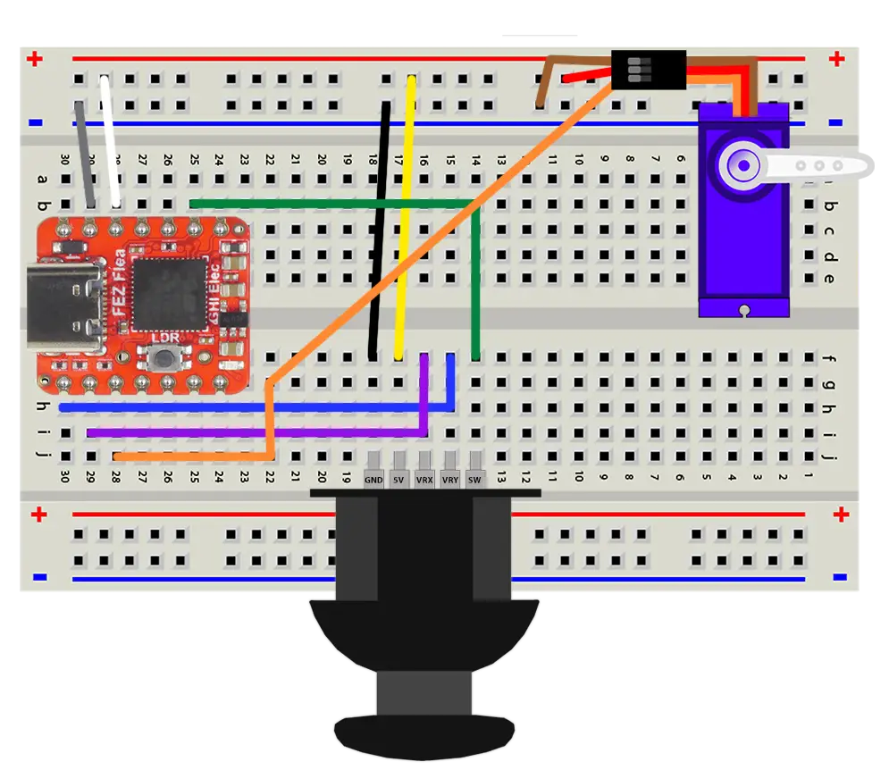
- Clear the photoresistor and LED from the last lesson.
- Plug the joystick's five pins into five breadboard rows (use pin-to-socket wires if it has a socket header).
- +5V → the + rail (3.3 V). GND → the − rail.
- VRx → PA0. VRy → PA4. SW → PB13.
- Wire the servo as in Servo Motor: orange → PA1, red → 5V, brown → the − rail.
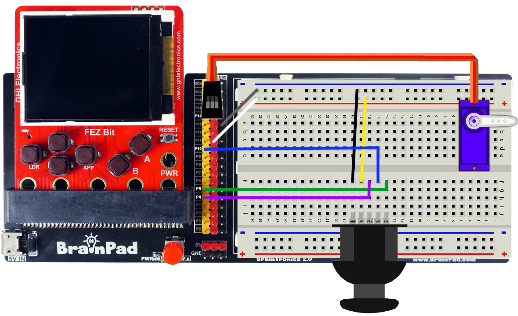
- Clear the photoresistor and LED from the last lesson.
- Plug the joystick's five pins into five breadboard rows (use pin-to-socket wires if it has a socket header).
- +5V → the + rail (3.3 V). GND → the − rail.
- VRx → header pin P4. VRy → P10. SW → P5.
- Wire the servo as in Servo Motor: orange → P14, red → the adapter's 5V, brown → the − rail.
Make sure the + rail really is connected to 3.3V and not 5V before powering up.
Step 3 — Read both axes
Two channels on the same ADC controller, read one after the other:
- FEZ Flea
- FEZ Bit
using System.Diagnostics;
using System.Threading;
using GHIElectronics.TinyCLR.Devices.Adc;
using GHIElectronics.TinyCLR.Pins;

var adc = AdcController.FromName(FEZFlea.Adc.Controller1.Id);

var xAxis = adc.OpenChannel(FEZFlea.Adc.Controller1.PA0);
var yAxis = adc.OpenChannel(FEZFlea.Adc.Controller1.PA4);

while (true) {
    double x = xAxis.ReadRatio();
    double y = yAxis.ReadRatio();

    Debug.WriteLine("X: " + x.ToString("N2") + "   Y: " + y.ToString("N2"));
    Thread.Sleep(200);
}
using System.Diagnostics;
using System.Threading;
using GHIElectronics.TinyCLR.Devices.Adc;
using GHIElectronics.TinyCLR.Pins;

var adc = AdcController.FromName(FEZBit.Adc.Controller1.Id);

var xAxis = adc.OpenChannel(FEZBit.Adc.Controller1.P4);
var yAxis = adc.OpenChannel(FEZBit.Adc.Controller1.P10);

while (true) {
    double x = xAxis.ReadRatio();
    double y = yAxis.ReadRatio();

    Debug.WriteLine("X: " + x.ToString("N2") + "   Y: " + y.ToString("N2"));
    Thread.Sleep(200);
}
Press F5 and push the stick around. Both numbers run from about 0.00 to 1.00, and when you let go they spring back to roughly 0.50 — roughly, not exactly. A reading of 0.48 or 0.53 at rest is normal.
Check which way is which: if pushing right makes Y move instead of X, swap the two wires (or swap the two lines of code). If a direction counts backwards, that axis is simply wired the other way round — Analog Input explains why, and you can fix it in code with 1 - x.
Step 4 — Center it, and add a dead zone
A resting value of "about 0.5" is awkward to work with. Convert each axis to a signed number instead: −1.0 full one way, 0.0 centered, +1.0 full the other.
Then handle the wobble. Let go of the stick and the readings don't settle on one number — they drift by a few hundredths. Feed that into a servo and the arm twitches forever. A dead zone treats anything near the center as exactly zero:
const double DeadZone = 0.08;       // ignore movement smaller than this

while (true) {
    double x = Signed(xAxis.ReadRatio());
    double y = Signed(yAxis.ReadRatio());

    Debug.WriteLine("X: " + x.ToString("N2") + "   Y: " + y.ToString("N2"));
    Thread.Sleep(100);
}

// Convert 0.0…1.0 into -1.0…+1.0, with a dead zone around the center.
double Signed(double ratio) {
    double value = (ratio - 0.5) * 2;

    if (value > -DeadZone && value < DeadZone) {
        return 0;
    }

    return value;
}
Replace the while loop with it and press F5. Let go of the stick: both axes read a clean 0.00. Push it slightly: nothing happens until you pass the dead zone, then the numbers climb smoothly.
If your stick still reads non-zero at rest, widen DeadZone a little. If small movements feel ignored, narrow it.
Step 5 — Steer the servo
Now map the X axis onto the servo's 0°–180° range, with center stick pointing the arm straight ahead:
- FEZ Flea
- FEZ Bit
using System.Device.Pwm;
using System.Diagnostics;
using System.Threading;
using GHIElectronics.TinyCLR.Devices.Adc;
using GHIElectronics.TinyCLR.Pins;

var adc = AdcController.FromName(FEZFlea.Adc.Controller1.Id);

var xAxis = adc.OpenChannel(FEZFlea.Adc.Controller1.PA0);
var yAxis = adc.OpenChannel(FEZFlea.Adc.Controller1.PA4);

using PwmChannel servo = PwmChannel.Create(
    FEZFlea.Timer.Pwm.Controller2.Chip,
    FEZFlea.Timer.Pwm.Controller2.PA1,
    50,
    0.075);

servo.Start();

// From your calibration in the Servo Motor lesson.
const double MinPulse = 0.5;
const double MaxPulse = 2.5;
const double Period = 20.0;
const double DeadZone = 0.08;

while (true) {
    double x = Signed(xAxis.ReadRatio());

    // -1…+1 becomes 0°…180°.
    double angle = (x + 1) * 90;

    SetAngle(angle);
    Debug.WriteLine("X: " + x.ToString("N2") + "   angle: " + angle.ToString("N0"));

    Thread.Sleep(20);
}

double Signed(double ratio) {
    double value = (ratio - 0.5) * 2;
    if (value > -DeadZone && value < DeadZone) return 0;
    return value;
}

void SetAngle(double degrees) {
    double pulse = MinPulse + (MaxPulse - MinPulse) * degrees / 180;
    servo.DutyCycle = pulse / Period;
}
using System.Device.Pwm;
using System.Diagnostics;
using System.Threading;
using GHIElectronics.TinyCLR.Devices.Adc;
using GHIElectronics.TinyCLR.Pins;

var adc = AdcController.FromName(FEZBit.Adc.Controller1.Id);

var xAxis = adc.OpenChannel(FEZBit.Adc.Controller1.P4);
var yAxis = adc.OpenChannel(FEZBit.Adc.Controller1.P10);

using PwmChannel servo = PwmChannel.Create(
    FEZBit.Timer.Pwm.Controller13.Chip,
    FEZBit.Timer.Pwm.Controller13.P14,
    50,
    0.075);

servo.Start();

// From your calibration in the Servo Motor lesson.
const double MinPulse = 0.5;
const double MaxPulse = 2.5;
const double Period = 20.0;
const double DeadZone = 0.08;

while (true) {
    double x = Signed(xAxis.ReadRatio());

    // -1…+1 becomes 0°…180°.
    double angle = (x + 1) * 90;

    SetAngle(angle);
    Debug.WriteLine("X: " + x.ToString("N2") + "   angle: " + angle.ToString("N0"));

    Thread.Sleep(20);
}

double Signed(double ratio) {
    double value = (ratio - 0.5) * 2;
    if (value > -DeadZone && value < DeadZone) return 0;
    return value;
}

void SetAngle(double degrees) {
    double pulse = MinPulse + (MaxPulse - MinPulse) * degrees / 180;
    servo.DutyCycle = pulse / Period;
}
Press F5 and move the stick left and right. The arm follows your thumb, and snaps back to 90° when you let go.
Try the debugger: set a breakpoint on SetAngle(angle);, hold the stick somewhere, and press F5. The arm steps to exactly the angle in the Locals window, and holds there while you think about it — the input, the number, and the motion all frozen at the same instant.
Step 6 — Use the button
The stick's shaft pushes a plain button, wired to ground — exactly like the buttons in Digital Input. Use it to park the servo at center, whatever the stick is doing:
using GpioController gpio = new GpioController();

int buttonPin = FEZFlea.GpioPin.PB13;       // FEZ Bit: FEZBit.GpioPin.P5
gpio.OpenPin(buttonPin, PinMode.InputPullUp);
Then inside the loop, before moving the servo:
bool parked = gpio.Read(buttonPin) == PinValue.Low;
double angle = parked ? 90 : (Signed(xAxis.ReadRatio()) + 1) * 90;
Add using System.Device.Gpio; at the top. Press F5: steer with the stick, and press down on it to snap the arm back to center.
How it works
A joystick is two potentiometers
Under the cap are two potentiometers on a gimbal, one for each axis, with springs that return the shaft to the middle. Push the stick and the shaft turns one or both wipers. Electrically, Analog Input already covered everything it does.
That's also why the +5V label doesn't force 5 V on you. The pin just feeds the top of both dividers, and the outputs scale with whatever you supply. Power it from 3.3 V and the full range of travel fits neatly inside the ADC's range.
Center-resting sensors
Any sensor that rests in the middle — joysticks, some rotary controls, current sensors — reads about half of its range at rest. Two small conversions make it usable:
signed = (ratio − 0.5) × 2        →  -1.0 … +1.0
output = (signed + 1) × 90        →  0° … 180°
The first line shifts and scales. The second maps onto whatever the output needs: servo angles here, motor speed or screen coordinates elsewhere.
Dead zones
A spring-centered stick doesn't return to exactly the same spot, and the ADC adds its own jitter. Without a dead zone, a resting stick still produces small non-zero values that a servo will faithfully follow, and a twitching servo consumes current and wears out.
Game controllers do exactly this, which is why a worn controller "drifts": its dead zone is no longer big enough to hide the slop in a stick.
Too wide and small movements go missing; too narrow and it twitches. Start with 5–10% and adjust by feel.
Try this
- Two axes, two outputs. Add the RGB module from RGB LEDs and use X for red and Y for blue, so the color follows the stick.
- Speed, not position. Instead of setting the angle directly, make the stick set a rate: hold right and the arm keeps moving right until you let go. This is how continuous-rotation servos and motors are driven.
- Calibrate the center. Read both axes once at startup, while the stick is untouched, and use those numbers as the true center instead of 0.5.
- Sound effects. Map the Y axis onto the buzzer's pitch from Sound for a thumb theremin.
Next
Distance Sensor: measure how far away something is by timing an ultrasonic echo — and meet a sensor that needs 5 V.
Something not working, or a step unclear? Ask in the TinyCLR forum — we read every post.