Distance Sensor

Bats do it, ships do it, and so does the sensor in the kit: send out a sound pulse, wait for the echo, and work out the distance from how long it took. The HC-SR04 does the ultrasound part; your code does the timing and the arithmetic.
This is also the lesson where a part needs 5 V, which is a good moment to learn what "5 V tolerant" means.
About 35 minutes.
What you'll learn
- How an ultrasonic sensor measures distance by timing an echo
- How to measure a pulse in microseconds without writing timing code yourself
- How to convert time into distance using the speed of sound
- What 5 V tolerance means — and what it does not mean
What you'll need
- From the kit:
- HC-SR04 ultrasonic distance sensor
- Piezo buzzer
- Jumper wires
Pin reference
| HC-SR04 pin | FEZ Flea | FEZ Bit |
|---|---|---|
| Trig | PB14 | P6 |
| Echo | PB15 | P7 |
| VCC | 5V | 5V (adapter) |
| GND | GND | GND |
| Also used | FEZ Flea | FEZ Bit |
|---|---|---|
| Buzzer + | PB8 | P2 |
Step 1 — Create the project
Create a new TinyCLR Application project and install GHIElectronics.TinyCLR.Devices.Signals, GHIElectronics.TinyCLR.Devices.Gpio, GHIElectronics.TinyCLR.Devices.Pwm, and GHIElectronics.TinyCLR.Pins.
Need the steps? Start Here covers creating a project and deploying.
This lesson uses TinyCLR's own GPIO API — GHIElectronics.TinyCLR.Devices.Gpio — instead of the .NET IoT one, because the pulse-timing class takes its pins in that form. Both live in the same NuGet package, so nothing extra to install.
Step 2 — Wire the sensor
With USB unplugged:
- FEZ Flea
- FEZ Bit
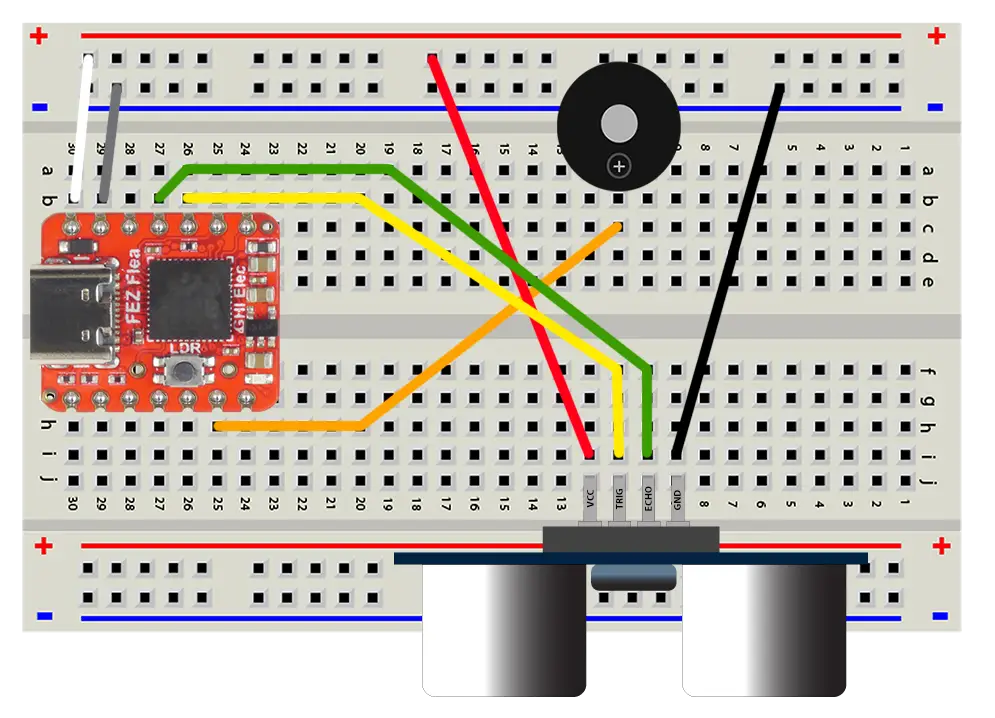
- Clear the joystick and servo from the last lesson.
- Add a buzzer on PB8 and - rail.
- Plug the sensor into the breadboard, or use pin-to-socket wires to reach its four pins.
- VCC → the Flea's 5V pin. GND → the − rail.
- Trig → PB14. Echo → PB15.
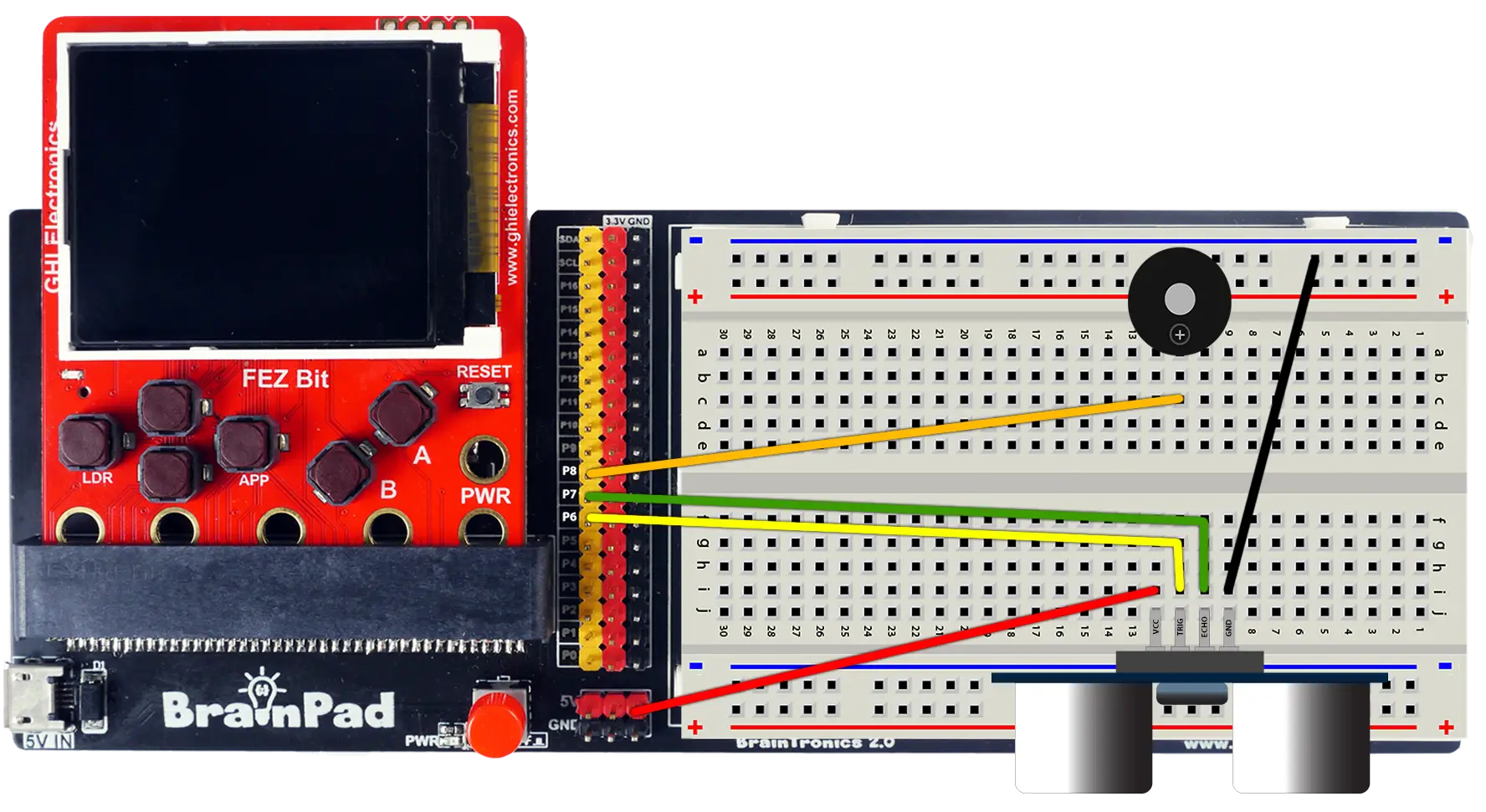
- Clear the joystick and servo from the last lesson. Keep the buzzer on P2 if it's still wired.
- Add a buzzer on PB8 and - rail.
- Plug the sensor into the breadboard, or use pin-to-socket wires to reach its four pins.
- VCC → the adapter's 5V header pin. GND → the − rail.
- Trig → header pin P6. Echo → P7.
The HC-SR04 needs a 5 V supply — it won't work reliably on 3.3 V. Its Echo pin therefore sends out a 5 V signal, and it connects to your board directly: SITCore pins are 5 V tolerant. See below for what that does and doesn't allow.
Step 3 — Measure the echo
The sensor works in two steps: you pulse Trig high for at least 10 µs, and it replies by holding Echo high for exactly as long as the sound takes to travel out and back.
Ten microseconds is far too short to produce with Thread.Sleep, and timing the echo in a loop would be hopeless. PulseFeedback does both in hardware-assisted form: one call sends the trigger and returns how long the echo lasted.
- FEZ Flea
- FEZ Bit
using System;
using System.Diagnostics;
using System.Threading;
using GHIElectronics.TinyCLR.Devices.Gpio;
using GHIElectronics.TinyCLR.Devices.Signals;
using GHIElectronics.TinyCLR.Pins;

var gpio = GpioController.GetDefault();

var trigger = gpio.OpenPin(FEZFlea.GpioPin.PB14);
var echo = gpio.OpenPin(FEZFlea.GpioPin.PB15);

var sensor = new PulseFeedback(trigger, echo, PulseFeedbackMode.EchoDuration) {
    DisableInterrupts = false,
    Timeout = TimeSpan.FromSeconds(1),
    PulseLength = TimeSpan.FromTicks(100),      // 10 µs trigger pulse
    PulseValue = GpioPinValue.High,             // trigger is an active-high pulse
    EchoValue = GpioPinValue.High,              // measure how long echo stays high
};

while (true) {
    TimeSpan echoTime = sensor.Trigger();

    double microseconds = echoTime.TotalMilliseconds * 1000;
    double centimeters = microseconds * 0.0343 / 2;

    Debug.WriteLine("Echo: " + microseconds.ToString("N0") + " µs   " +
                    "Distance: " + centimeters.ToString("N1") + " cm");

    Thread.Sleep(200);
}
using System;
using System.Diagnostics;
using System.Threading;
using GHIElectronics.TinyCLR.Devices.Gpio;
using GHIElectronics.TinyCLR.Devices.Signals;
using GHIElectronics.TinyCLR.Pins;

var gpio = GpioController.GetDefault();

var trigger = gpio.OpenPin(FEZBit.GpioPin.P6);
var echo = gpio.OpenPin(FEZBit.GpioPin.P7);

var sensor = new PulseFeedback(trigger, echo, PulseFeedbackMode.EchoDuration) {
    DisableInterrupts = false,
    Timeout = TimeSpan.FromSeconds(1),
    PulseLength = TimeSpan.FromTicks(100),      // 10 µs trigger pulse
    PulseValue = GpioPinValue.High,             // trigger is an active-high pulse
    EchoValue = GpioPinValue.High,              // measure how long echo stays high
};

while (true) {
    TimeSpan echoTime = sensor.Trigger();

    double microseconds = echoTime.TotalMilliseconds * 1000;
    double centimeters = microseconds * 0.0343 / 2;

    Debug.WriteLine("Echo: " + microseconds.ToString("N0") + " µs   " +
                    "Distance: " + centimeters.ToString("N1") + " cm");

    Thread.Sleep(200);
}
Press F5 and hold your hand in front of the sensor. Move it closer and further, and check the numbers against a ruler.
PulseLengthis the trigger pulse. One tick is 100 ns, so 100 ticks is 10 µs.Trigger()does the whole exchange and hands back the echo duration.Timeoutcaps how long it waits. Nothing to bounce off means no echo — aim it at an open room and the readings stop making sense.
Try the debugger: set a breakpoint on Debug.WriteLine(...), hold your hand at a fixed distance, and press F5 a few times. microseconds and centimeters in the Locals window show one complete measurement each time — and you'll see a little variation between identical-looking readings.
Step 4 — Where the numbers come from
Sound travels about 343 metres per second in room-temperature air, which is 0.0343 cm per microsecond. The echo made the trip twice — out to the object and back — so half the time is the distance:
centimeters = microseconds × 0.0343 ÷ 2
A few numbers worth knowing:
| Distance | Echo duration |
|---|---|
| 5 cm | ~290 µs |
| 50 cm | ~2,900 µs |
| 2 m | ~11,700 µs |
For inches, divide the centimeters by 2.54 — or use 0.0135 inches per microsecond in the formula.
Step 5 — Build a parking sensor
Readings become useful when something reacts to them. This version beeps faster the closer an object gets, like the sensor on a car bumper. Add to the top of your program:
- FEZ Flea
- FEZ Bit
using System.Device.Pwm;

using PwmChannel buzzer = PwmChannel.Create(
    FEZFlea.Timer.Pwm.Controller16.Chip,
    FEZFlea.Timer.Pwm.Controller16.PB8,
    2000,
    0);

buzzer.Start();
using System.Device.Pwm;

using PwmChannel buzzer = PwmChannel.Create(
    FEZBit.Timer.Pwm.Controller5.Chip,
    FEZBit.Timer.Pwm.Controller5.P2,
    2000,
    0);

buzzer.Start();
Then replace the while loop with:
while (true) {
    double microseconds = sensor.Trigger().TotalMilliseconds * 1000;
    double centimeters = microseconds * 0.0343 / 2;

    Debug.WriteLine("Distance: " + centimeters.ToString("N1") + " cm");

    if (centimeters < 5) {
        // Very close: one continuous tone.
        buzzer.DutyCycle = 0.5;
        Thread.Sleep(200);
    } else if (centimeters < 60) {
        // Closer means a shorter gap between beeps.
        buzzer.DutyCycle = 0.5;
        Thread.Sleep(30);

        buzzer.DutyCycle = 0;
        Thread.Sleep((int)(centimeters * 8));
    } else {
        // Nothing nearby: stay quiet.
        buzzer.DutyCycle = 0;
        Thread.Sleep(200);
    }
}
Press F5 and walk your hand toward the sensor. The beeps speed up as you approach, then run together into one tone.
Step 6 — A radar is a distance sensor that moves
Radar displays look impressive, but the idea is simple: a distance sensor that points somewhere different each time it measures. Mount the HC-SR04 on the servo from Servo Motor, and at every angle in a sweep, take a reading. Angle plus distance describes a point — and a series of them describes the room.
Nothing new is needed to build it: the servo sweep from that lesson, plus the measurement from this one. Print each angle and distance to the Output window, or draw them on a screen once you've done Displays.
Watch for two practical details. Give the servo a moment to settle before measuring, since a moving sensor hears its own echo from the wrong direction. And the beam is wide, so a sweep sees a smeared shape rather than a crisp outline.
How it works
Ultrasound
The sensor's two cylinders are a speaker and a microphone, working at 40 kHz — well above human hearing, so all of this is silent to you. A trigger pulse makes the speaker emit a short burst of clicks, and the chip holds Echo high until the microphone hears them come back.
Trig   ▁▇▁▁▁▁▁▁▁▁▁▁▁▁▁▁▁▁▁▁▁▁▁▁▁▁▁▁▁▁▁▁▁▁▁   10 µs pulse from your board
Echo   ▁▁▁▇▇▇▇▇▇▇▇▇▇▇▇▇▁▁▁▁▁▁▁▁▁▁▁▁▁▁▁▁▁▁▁   sensor holds this high for the round trip
The practical range is roughly 2 cm to 4 m. Closer than 2 cm, the echo returns before the sensor is listening. Further than 4 m, too little sound comes back.
What it's good at: flat, hard surfaces facing it. What it struggles with: soft fabric and foam, which absorb the sound; surfaces at an angle, which bounce it away; and small objects, which the wide beam (roughly 15°) tends to miss between larger ones.
Temperature matters
The speed of sound depends on air temperature — about 0.6 m/s faster per degree Celsius. From a cold morning to a hot afternoon, that's about a 2% shift, which is 2 cm over a metre. Good enough for a parking sensor, and something to correct for if you ever need better than a few percent.
5 V tolerance
Your board runs at 3.3 V: its pins drive 3.3 V when high, and expect no more than that on an input. 5 V tolerant means the input pins can accept a 5 V signal anyway, without damage — which is why the sensor's 5 V Echo output connects straight to a pin, with no divider.
Two things it does not mean:
- You can't power the board from 5 V. Tolerance applies to input pins only.
- Your board can't send 5 V. Output pins still drive 3.3 V. That's fine here: the HC-SR04 reads anything above about 2 V as high, so a 3.3 V trigger works. Some 5 V parts don't, and they need a level shifter.
GPIO has the full details.
Try this
- Tape measure. Average ten readings and print the result to one decimal place. Compare it with a ruler at 10 cm, 50 cm and 1 m, and see where it drifts.
- Steady the edge. A threshold at "closer than 30 cm" will chatter when something sits right at 30 cm. Apply the hysteresis from Light and Logic.
- Invisible tripwire. Watch for a sudden drop in distance and sound an alarm — a doorway counter, or a drawer alarm.
- Theremin. Map distance onto the buzzer's pitch from Sound and play it by waving your hand.
- Radar sweep. Build Step 6 for real: sweep the servo and print an angle-and-distance table.
Next
Displays: give your board a screen, so it can show readings without a PC attached.
Something not working, or a step unclear? Ask in the TinyCLR forum — we read every post.