Displays

Every lesson so far has reported its results to Visual Studio. Unplug the USB cable and your project goes quiet. A screen changes that: the board shows its own readings, and becomes something you can put on a shelf.
This lesson wires a common I²C OLED to either board and draws on it with BasicGraphics — text, shapes, a live sensor readout, and a scrolling graph.
About 45 minutes.
This lesson needs an SSD1306 OLED, the small monochrome 128×64 screen sold everywhere for a few dollars. Get the I²C version, which has four pins: GND, VCC, SCL, SDA.
Using a FEZ Bit? It already has a color screen built in — FEZ Bit Screen does this lesson on that, with no extra parts. This lesson still works on the Bit if you have an OLED.
What you'll learn
- How to talk to a display over I²C, using only two signal wires
- How BasicGraphics draws into a buffer, and why nothing appears until you send it
- How to lay out a readable readout on a tiny screen
- How to plot a live graph of a sensor
What you'll need
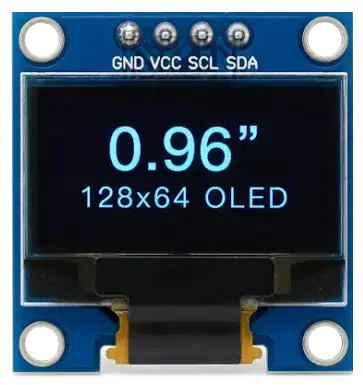
- An SSD1306 128×64 I²C OLED
- From the kit:
- Light sensor (photoresistor) and 1× 27 kΩ resistor — the divider from Light and Logic
- Jumper wires
Pin reference
| OLED pin | FEZ Flea | FEZ Bit |
|---|---|---|
| SDA (data) | PB9 | SDA(P20) |
| SCL/SCK (clock) | PB8 | SCL(P19) |
| VCC/VDD | 3V3 | 3.3V (adapter) |
| GND | GND | GND |
| Also used | FEZ Flea | FEZ Bit |
|---|---|---|
| Photoresistor divider | PA4 | P10 |
Step 1 — Create the project
Create a new TinyCLR Application project and install:
Need the steps? Start Here covers creating a project and deploying.
GHIElectronics.TinyCLR.Drivers.SolomonSystech.SSD1306— the display driverGHIElectronics.TinyCLR.Drivers.BasicGraphics— the drawing libraryGHIElectronics.TinyCLR.Devices.I2c— the bus the display usesGHIElectronics.TinyCLR.Devices.Adc— for the sensor, laterGHIElectronics.TinyCLR.Pins
Step 2 — Wire the display
I²C needs only two signal wires no matter how many devices share them: SDA carries data, SCL is the clock. Both must go to the pins that have those functions — unlike GPIO, you can't pick freely.
With USB unplugged:
- FEZ Flea
- FEZ Bit
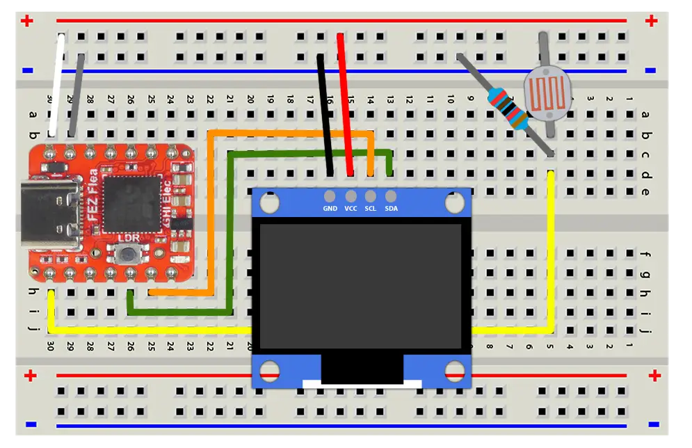
- VCC → the + rail (3.3 V). GND → the − rail.
- SDA → PB9. SCL → PB8.
- Rebuild the photoresistor divider from Light and Logic: photoresistor from + rail to a row, 27 kΩ from that row to −, and that row to PA4.
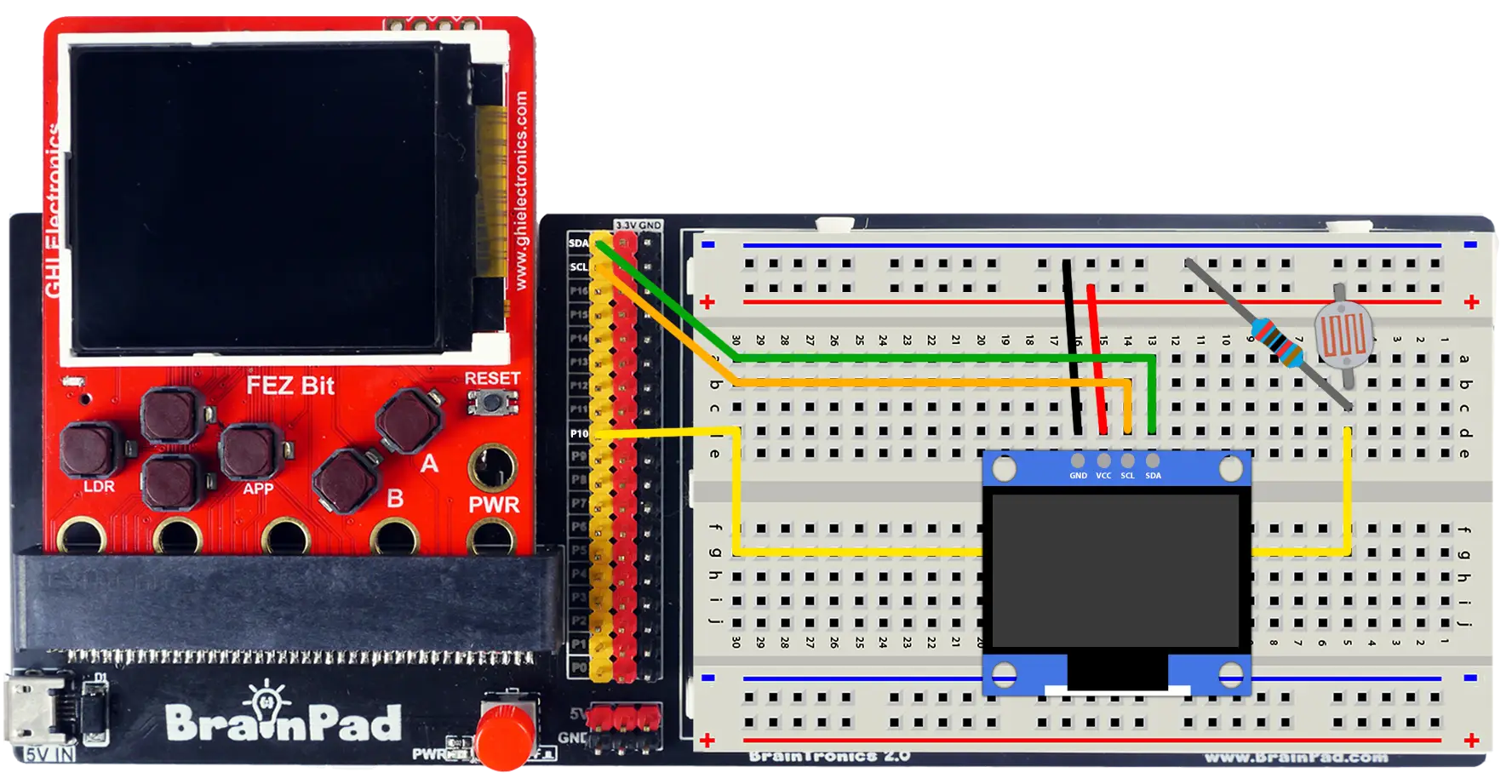
- VCC → the + rail (3.3 V). GND → the − rail.
- SDA → header pin SDA(P20). SCL → SCL(P19).
- Rebuild the photoresistor divider from Light and Logic: photoresistor from + rail to a row, 27 kΩ from that row to −, and that row to P10.
Most OLED modules have the I²C pull-up resistors on board, so nothing extra is needed. If yours is blank, add a 4.7 kΩ resistor from each of SDA and SCL to 3.3 V.
Step 3 — Hello, screen
- FEZ Flea
- FEZ Bit
using System.Threading;
using GHIElectronics.TinyCLR.Devices.I2c;
using GHIElectronics.TinyCLR.Drivers.BasicGraphics;
using GHIElectronics.TinyCLR.Drivers.SolomonSystech.SSD1306;
using GHIElectronics.TinyCLR.Pins;

const int Width = 128;
const int Height = 64;

var i2c = I2cController.FromName(FEZFlea.I2cBus.I2c1);
var oled = new SSD1306Controller(i2c.GetDevice(SSD1306Controller.GetConnectionSettings()));

var screen = new BasicGraphics(Width, Height, ColorFormat.OneBpp);
uint white = BasicGraphics.ColorFromRgb(255, 255, 255);

screen.Clear();
screen.DrawString("Hello!", white, 8, 8);
screen.DrawString("TinyCLR", white, 8, 28);

oled.DrawBufferNative(screen.Buffer);

Thread.Sleep(Timeout.Infinite);
using System.Threading;
using GHIElectronics.TinyCLR.Devices.I2c;
using GHIElectronics.TinyCLR.Drivers.BasicGraphics;
using GHIElectronics.TinyCLR.Drivers.SolomonSystech.SSD1306;
using GHIElectronics.TinyCLR.Pins;

const int Width = 128;
const int Height = 64;

var i2c = I2cController.FromName(FEZBit.I2cBus.Edge);
var oled = new SSD1306Controller(i2c.GetDevice(SSD1306Controller.GetConnectionSettings()));

var screen = new BasicGraphics(Width, Height, ColorFormat.OneBpp);
uint white = BasicGraphics.ColorFromRgb(255, 255, 255);

screen.Clear();
screen.DrawString("Hello!", white, 8, 8);
screen.DrawString("TinyCLR", white, 8, 28);

oled.DrawBufferNative(screen.Buffer);

Thread.Sleep(Timeout.Infinite);
Press F5. Two lines of text appear on the OLED.
BasicGraphicsholds a picture in memory — nothing on the display yet.ClearandDrawStringonly change those bytes.oled.DrawBufferNative(screen.Buffer)sends the whole picture over I²C. This is the moment the screen changes.ColorFormat.OneBppmeans one bit per pixel: lit or dark, which is all this screen can do. The buffer is 128 × 64 ÷ 8 = 1024 bytes.
Nothing on screen? Check SDA and SCL aren't swapped, and that the module is powered from 3.3 V.
Step 4 — Shapes, and the drawing loop
Draw a few shapes, and make it move:
int x = 0;

while (true) {
    screen.Clear();

    screen.DrawString("Shapes", white, 4, 2);
    screen.DrawRectangle(white, 4, 20, 40, 24);
    screen.DrawCircle(white, 76, 32, 12);
    screen.DrawLine(white, 0, 60, 127, 60);

    // A dot that walks across the bottom.
    screen.DrawCircle(white, x, 52, 3);
    x = (x + 4) % Width;

    oled.DrawBufferNative(screen.Buffer);
    Thread.Sleep(50);
}
Replace everything after the white line with this and press F5.
Every frame follows the same three beats: clear, draw, send. Forget the Clear and old frames pile up; forget DrawBufferNative and the screen freezes while your program happily draws to nothing.
Try the debugger: set a breakpoint on oled.DrawBufferNative(...) and press F5 repeatedly. Each press paints exactly one frame, and x in the Locals window matches the dot's position — animation, one step at a time.
Step 5 — A live sensor readout
Now the point of having a screen: show a reading without a PC attached. This puts the light level on screen as a number and a bar.
- FEZ Flea
- FEZ Bit
using System.Threading;
using GHIElectronics.TinyCLR.Devices.Adc;
using GHIElectronics.TinyCLR.Devices.I2c;
using GHIElectronics.TinyCLR.Drivers.BasicGraphics;
using GHIElectronics.TinyCLR.Drivers.SolomonSystech.SSD1306;
using GHIElectronics.TinyCLR.Pins;

const int Width = 128;
const int Height = 64;

var i2c = I2cController.FromName(FEZFlea.I2cBus.I2c1);
var adc = AdcController.FromName(FEZFlea.Adc.Controller1.Id);
var lightSensor = adc.OpenChannel(FEZFlea.Adc.Controller1.PA4);

var oled = new SSD1306Controller(i2c.GetDevice(SSD1306Controller.GetConnectionSettings()));

var screen = new BasicGraphics(Width, Height, ColorFormat.OneBpp);
uint white = BasicGraphics.ColorFromRgb(255, 255, 255);

while (true) {
    double light = ReadAverage(10);
    int percent = (int)(light * 100);

    screen.Clear();

    screen.DrawString("LIGHT", white, 4, 2);
    screen.DrawString(percent + " %", white, 4, 20);

    // A bar that fills with the reading.
    screen.DrawRectangle(white, 4, 44, 120, 12);
    for (int i = 0; i < percent * 116 / 100; i++) {
        screen.DrawLine(white, 6 + i, 46, 6 + i, 53);
    }

    oled.DrawBufferNative(screen.Buffer);
    Thread.Sleep(100);
}

double ReadAverage(int samples) {
    double total = 0;

    for (int i = 0; i < samples; i++) {
        total += lightSensor.ReadRatio();
    }

    return total / samples;
}
using System.Threading;
using GHIElectronics.TinyCLR.Devices.Adc;
using GHIElectronics.TinyCLR.Devices.I2c;
using GHIElectronics.TinyCLR.Drivers.BasicGraphics;
using GHIElectronics.TinyCLR.Drivers.SolomonSystech.SSD1306;
using GHIElectronics.TinyCLR.Pins;

const int Width = 128;
const int Height = 64;

var i2c = I2cController.FromName(FEZBit.I2cBus.Edge);
var adc = AdcController.FromName(FEZBit.Adc.Controller1.Id);
var lightSensor = adc.OpenChannel(FEZBit.Adc.Controller1.P10);

var oled = new SSD1306Controller(i2c.GetDevice(SSD1306Controller.GetConnectionSettings()));

var screen = new BasicGraphics(Width, Height, ColorFormat.OneBpp);
uint white = BasicGraphics.ColorFromRgb(255, 255, 255);

while (true) {
    double light = ReadAverage(10);
    int percent = (int)(light * 100);

    screen.Clear();

    screen.DrawString("LIGHT", white, 4, 2);
    screen.DrawString(percent + " %", white, 4, 20);

    // A bar that fills with the reading.
    screen.DrawRectangle(white, 4, 44, 120, 12);
    for (int i = 0; i < percent * 116 / 100; i++) {
        screen.DrawLine(white, 6 + i, 46, 6 + i, 53);
    }

    oled.DrawBufferNative(screen.Buffer);
    Thread.Sleep(100);
}

double ReadAverage(int samples) {
    double total = 0;

    for (int i = 0; i < samples; i++) {
        total += lightSensor.ReadRatio();
    }

    return total / samples;
}
Press F5 and move your hand over the sensor. The number and the bar follow it.
Two small layout habits worth keeping: a label so the number means something, and a bar, because a shape is easier to read at a glance than digits that change ten times a second.
Step 6 — A scrolling graph
A single number tells you now. A graph tells you what happened. Keep the last 128 readings — one per column — and slide them along:
int[] history = new int[Width];

while (true) {
    double light = ReadAverage(10);

    // Shift everything left by one, newest on the right.
    for (int i = 0; i < Width - 1; i++) {
        history[i] = history[i + 1];
    }
    history[Width - 1] = (int)(light * 40);     // 0…40 pixels tall

    screen.Clear();
    screen.DrawString("LIGHT " + (int)(light * 100) + "%", white, 2, 2);
    screen.DrawLine(white, 0, 62, 127, 62);      // baseline

    for (int i = 0; i < Width; i++) {
        screen.SetPixel(i, 61 - history[i], white);
    }

    oled.DrawBufferNative(screen.Buffer);
    Thread.Sleep(100);
}
Press F5 and wave your hand over the sensor, or walk past a lamp. The trace scrolls right to left, and about 13 seconds of history fits on screen.
This is the shape of every data logger: sample, store, shift, draw.
How it works
I²C in one minute
I²C connects many devices to the same two wires. SCL is a clock the board generates; SDA carries the bits. Every device has an address, and a message begins with the address of whoever it's for — so the OLED ignores traffic meant for a sensor sharing the same pins.
SSD1306Controller.GetConnectionSettings() fills in the display's address and speed, which is why you never see them in the code. Adding an I²C sensor later means another GetDevice call on the same controller, and no more wires.
Unlike GPIO or PWM, the pins aren't yours to choose: SDA and SCL are fixed by the chip, which is why the pin reference names exactly two.
Buffer, then send
BasicGraphics never touches the display. It owns an array of bytes and draws into it, and Buffer hands you that array so a display driver can send it.
That separation is why the same drawing code can target an OLED, a color LCD, or an LED matrix. It's also why every frame ends with DrawBufferNative: an update is one transfer of the whole picture, which keeps the screen from showing half-drawn frames.
In OneBpp mode, each byte holds eight vertically stacked pixels — the layout the SSD1306 expects, so no conversion is needed between the two.
Drawing on a small screen
128×64 pixels is about 21 characters across in the built-in font. A few habits help:
- Label every number.
"LIGHT 42%"beats"42". - Round aggressively.
(int)(light * 100)is more readable than four decimals that flicker. - Use a shape for the trend and digits for the value. The bar in Step 5 reads instantly; the number is there when you want precision.
Bigger screens
The SSD1306 is monochrome and small on purpose: it's cheap and needs two wires. Color displays with more pixels connect over SPI and are driven the same way — BasicGraphics in Rgb565 mode, or the full graphics engine on SC20xxx hardware. FEZ Bit Screen does exactly that on the Bit's built-in display, and Extended Features → Displays lists the other supported controllers.
Try this
- Distance meter. Swap the photoresistor for the Distance Sensor and show centimeters with a bar that grows as things get closer.
- Two readings at once. Split the screen: light on the top half, distance on the bottom.
- Night-light status. Bring back the hysteresis from Light and Logic and print
DARKorLIGHT, so you can see the decision as well as the number. - Min and max. Track the lowest and highest readings since power-up and show them in a corner.
- Stopwatch. Add a button from Digital Input: press to start, press to stop, with the elapsed time on screen.
Next
FEZ Bit Screen: the same readout on the FEZ Bit's built-in color display, using TinyCLR's full graphics engine.
Something not working, or a step unclear? Ask in the TinyCLR forum — we read every post.