Digital Output

Your first circuit: an LED on the breadboard, switched on and off from C#. Along the way you'll learn what a digital output actually does, why every LED needs a resistor, and — the best part — what it feels like to pause real hardware with a breakpoint.
About 20 minutes.
What you'll learn
- What a digital output is, and what
PinValue.HighandPinValue.Lowmean electrically - How to wire an LED with a current-limiting resistor, and why 220 Ω is a safe value
- How to step through hardware code with the debugger and watch the LED follow each line
What you'll need
- The Start Here setup done — the on-board LED blinked in Getting Started
- From the kit:
- Your board, breadboard, and USB cable(s)
- 1× LED (any color)
- 1× 220 Ω resistor — marked
220Ron the paper strip - Jumper wires — 1× pin-to-pin for the FEZ Flea, 2× pin-to-socket for the FEZ Bit
First time with these parts?
- LED — the longer leg is the positive side (anode) and goes toward the pin; the shorter leg, next to the flat edge of the rim, goes toward GND. In backwards it just stays dark, so nothing is harmed.
- Resistor — no polarity, so either way round works. The kit's resistors have five bands, while most charts online show four: 220 Ω is red · red · black · black · brown, and 27 kΩ is red · violet · black · red · brown.
220Ron the paper strip means 220 Ω — the letter sits where the decimal point would go.27Kis 27 kΩ.
More in Start Here → Parts you'll meet first.
Pin reference
| Connection | FEZ Flea | FEZ Bit |
|---|---|---|
| LED signal (through the resistor) | PA3 | P0 |
| LED ground | GND | GND |
Both pins also support PWM, so this same wiring carries straight into the Breathing LED lesson.
Step 1 — Create the project
- Create a new TinyCLR Application project, as in Getting Started.
- Install the
GHIElectronics.TinyCLR.Devices.GpioandGHIElectronics.TinyCLR.PinsNuGet packages.
Need the steps? Start Here covers creating a project and deploying.
Step 2 — The same blink, in the API this lab uses
You've already blinked the on-board LED in Getting Started, and that page offered two GPIO APIs to do it with. Every lesson from here uses the .NET IoT one — System.Device.Gpio, the same API you'd write against on a Raspberry Pi running full .NET. Both live in the package you just installed, so nothing changes but the spelling.
Starting from the program you already know also means the board proves itself before any wiring is involved. Replace Program.cs with:
- FEZ Flea
- FEZ Bit
using System.Device.Gpio;
using System.Threading;
using GHIElectronics.TinyCLR.Pins;

using GpioController controller = new GpioController();

int ledPin = FEZFlea.GpioPin.Led;
controller.OpenPin(ledPin, PinMode.Output);

while (true) {
    controller.Write(ledPin, PinValue.High);
    Thread.Sleep(500);

    controller.Write(ledPin, PinValue.Low);
    Thread.Sleep(500);
}
using System.Device.Gpio;
using System.Threading;
using GHIElectronics.TinyCLR.Pins;

using GpioController controller = new GpioController();

int ledPin = FEZBit.GpioPin.Led;
controller.OpenPin(ledPin, PinMode.Output);

while (true) {
    controller.Write(ledPin, PinValue.High);
    Thread.Sleep(500);

    controller.Write(ledPin, PinValue.Low);
    Thread.Sleep(500);
}
Press F5. The on-board LED blinks once a second.
Same LED, same blink — here's what the .NET IoT version is saying:
new GpioController()is the object you ask for pins, instead ofGpioController.GetDefault().OpenPin(ledPin, PinMode.Output)claims the pin and makes it an output in one call — the chip will drive its voltage.Write(ledPin, PinValue.High)sets the pin to 3.3 V;PinValue.Lowsets it to 0 V. The pin comes along on every call, because the controller holds them all rather than handing you a pin object.Thread.Sleep(500)waits half a second. Without it, the LED would switch thousands of times a second — too fast to see.
The highlighted line is the only one that changes between boards — everything else in the lessons is the same C#.
Stop the program (Shift+F5) before wiring. Next it moves off the board and onto the breadboard, where you decide which pin and which LED.
Step 3 — Wire the LED
With USB unplugged:
- FEZ Flea
- FEZ Bit

- Place the FEZ Flea so it straddles the center gap of the breadboard.
- Plug the resistor from the row of pin PA3 to an empty row. Resistors have no polarity, so either way round is fine.
- Plug the LED's long leg (anode) into the same row as the resistor's other end.
- Plug the LED's short leg (cathode) into another empty row.
- Use a jumper wire to connect the short leg's row to a GND pin.
FEZ Flea PA3 ──── 220 Ω resistor ────▶ LED ──── GND
                                   (long leg → short leg)
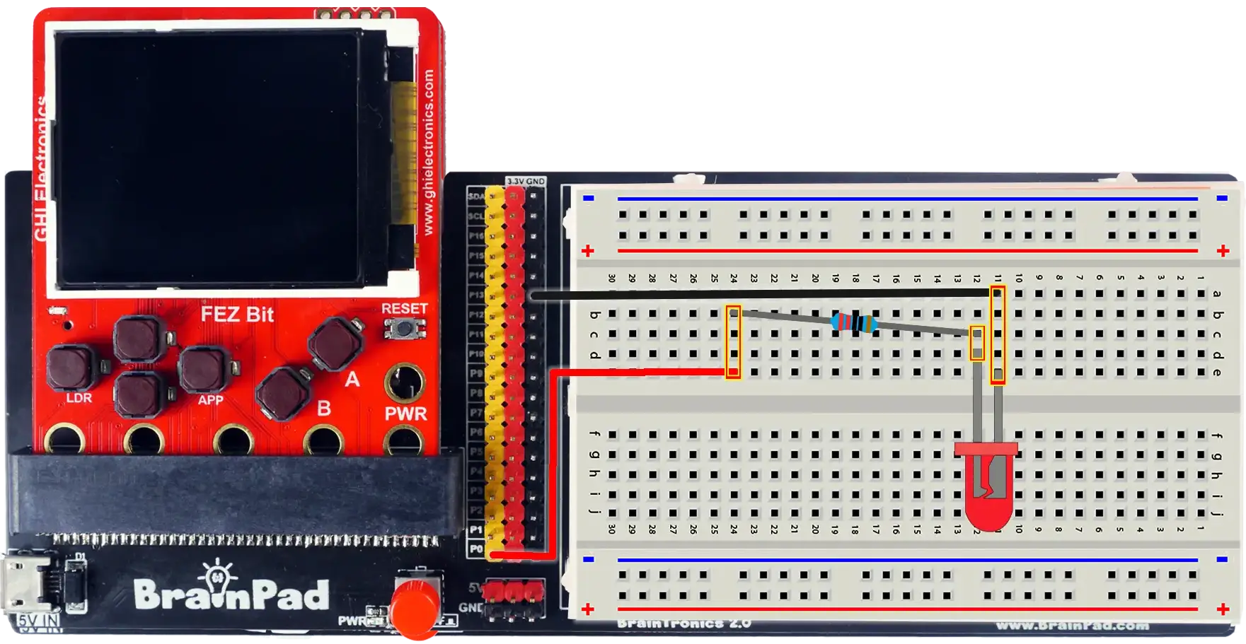
- Slide the FEZ Bit into the adapter board.
- Connect a pin-to-socket jumper wire from header pin P0 to an empty breadboard row.
- Plug the resistor from that row to another empty row. Resistors have no polarity, so either way round is fine.
- Plug the LED's long leg (anode) into the same row as the resistor's other end.
- Plug the LED's short leg (cathode) into another empty row.
- Connect a second pin-to-socket jumper wire from that row to a GND header pin.
FEZ Bit P0 ──── 220 Ω resistor ────▶ LED ──── GND
                                 (long leg → short leg)
Step 4 — Blink the breadboard LED
Point ledPin at the breadboard pin instead of the on-board LED, and add a counter so there's something to inspect in the next step:
- FEZ Flea
- FEZ Bit
using System.Device.Gpio;
using System.Threading;
using GHIElectronics.TinyCLR.Pins;

using GpioController controller = new GpioController();

int ledPin = FEZFlea.GpioPin.PA3;
controller.OpenPin(ledPin, PinMode.Output);

int blinkCount = 0;

while (true) {
    controller.Write(ledPin, PinValue.High);
    Thread.Sleep(500);

    controller.Write(ledPin, PinValue.Low);
    Thread.Sleep(500);

    blinkCount++;
}
using System.Device.Gpio;
using System.Threading;
using GHIElectronics.TinyCLR.Pins;

using GpioController controller = new GpioController();

int ledPin = FEZBit.GpioPin.P0;
controller.OpenPin(ledPin, PinMode.Output);

int blinkCount = 0;

while (true) {
    controller.Write(ledPin, PinValue.High);
    Thread.Sleep(500);

    controller.Write(ledPin, PinValue.Low);
    Thread.Sleep(500);

    blinkCount++;
}
Plug in USB (on the FEZ Bit, both cables) and press F5. The LED on the breadboard blinks.
Not blinking?
- LED backwards? Flip it — the long leg goes toward the resistor and the signal pin.
- Same row? Parts connect only when their legs share a row. Check that the resistor and LED long leg are in the same row, and the LED short leg and GND wire share another.
- Across the gap? Holes on opposite sides of the center gap aren't connected.
- Right pin? Compare against the pin reference and your board's pins.
Debug it
This is where the lab is different. The debugger isn't simulating anything — it's attached to your board, and when your code stops, the hardware stops with it.
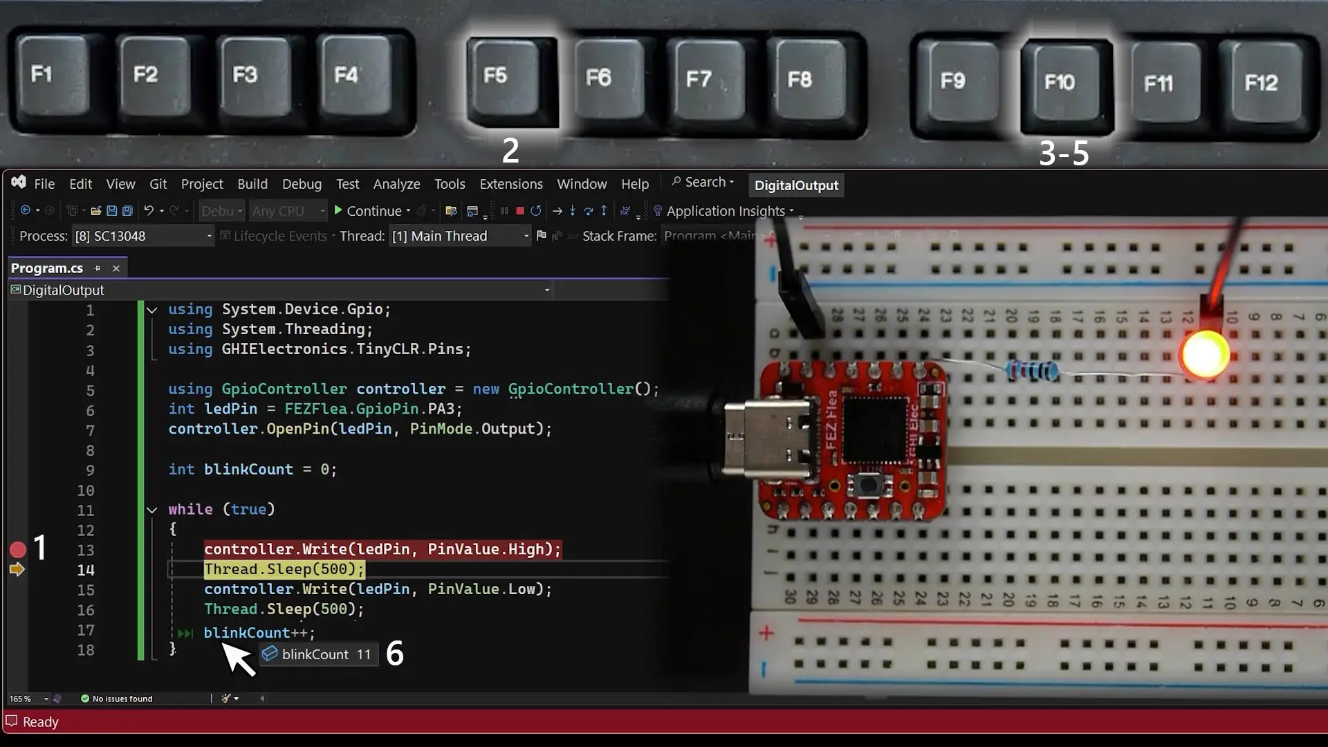
- Set a breakpoint. Click in the left margin next to
controller.Write(ledPin, PinValue.High);— a red dot appears. - Run. Press F5. The program stops on that line, highlighted in yellow. The LED is off — the line hasn't run yet.
- Step. Press F10 (Step Over). The line executes and the LED turns on — at the exact moment you pressed the key.
- Take your time. The LED stays on for as long as you leave the program paused — time is paused on the board, not just in the editor. Press F10 to run
Thread.Sleep(500). - Turn it off. Press F10 once more. The LED goes dark.
- Inspect. Hover over
blinkCountto see how many blinks have completed. Press F5 to continue — the program runs one more blink and stops at the breakpoint again. Hover again: the count has gone up by one. - Clean up. Click the red dot to remove the breakpoint, then press F5 to let it run freely.
You just single-stepped a circuit. The debugger works like this in every lesson — whenever something doesn't behave, set a breakpoint and look.
How it works
Digital output
A digital output has two states. High connects the pin to the chip's 3.3 V supply; Low connects it to 0 V (GND). When the pin is High, there's a 3.3 V difference between the pin and GND, so current flows through the resistor and the LED, and the LED lights. When the pin is Low, both ends are at 0 V — no current, no light.
Why the resistor matters
An LED isn't like a light bulb. Once the voltage across it passes a threshold — about 2 V for a red LED, around 3 V for blue and white — its resistance drops dramatically, and it will draw as much current as it can get. With nothing to limit it, that current can burn out the LED and overload the pin.
The resistor sets the current. Ohm's law — current = voltage ÷ resistance — tells you how much. The resistor sees whatever voltage the LED doesn't use:
current = (pin voltage − LED voltage) ÷ resistance
        = (3.3 V − 2.0 V) ÷ 220 Ω
        ≈ 6 mA
About 6 milliamps: plenty to see clearly, and well within what a microcontroller pin can supply.
Use a 220 Ω resistor with every LED in the lab. Its job is protection, not brightness — to control how bright an LED shines, you'll use PWM in the Breathing LED lesson.
Try this
- Two LEDs. Wire a second LED and 220 Ω resistor on PA2 (FEZ Flea) or P1 (FEZ Bit), and make the two alternate — one on while the other is off.
- SOS. Write a
Blink(int onMilliseconds)method and use it to flash · · · — — — · · · in Morse code: short blinks of 200 ms, long blinks of 600 ms. - Faster. Shrink both
Thread.Sleepvalues until the LED stops looking like it's blinking — somewhere around 10 ms it will look solid, just a little dimmer. Remember that: it's the idea behind Breathing LED.
Next
Digital Input — read buttons, learn why inputs need pull-ups, react to presses with events, and build a reaction-time game.
Something not working, or a step unclear? Ask in the TinyCLR forum — we read every post.