This lesson uses the color screen built into the FEZ Bit — no extra parts, and nothing to wire for the display itself. On a FEZ Flea, do Displays instead, which adds a small OLED.
FEZ Bit Screen
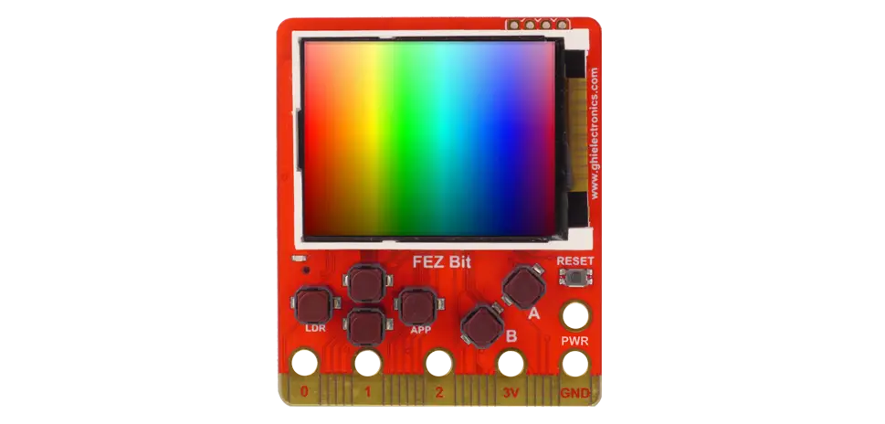
The FEZ Bit has a 160×128 color display on the front, wired to the board over SPI. Everything from Displays applies — draw into a buffer, then send it — with two differences: there's no wiring to do, and you have color to work with.
About 35 minutes.
What you'll learn
- How the FEZ Bit's built-in display is set up in code
- How to draw in color with
Rgb565 - How to lay out a color readout, and plot a graph with meaning in its colors
- Where TinyCLR's full graphics engine fits in
What you'll need
- A FEZ Bit and its adapter board
- From the kit:
- Light sensor (photoresistor) and 1× 27 kΩ resistor — the divider from Light and Logic
- Jumper wires
Pin reference
The display's pins are already connected inside the FEZ Bit, and the pin library names them:
| Display signal | Constant |
|---|---|
| SPI bus | FEZBit.SpiBus.Display |
| Chip select | FEZBit.GpioPin.DisplayChipselect |
| Register select | FEZBit.GpioPin.DisplayRs |
| Reset | FEZBit.GpioPin.DisplayReset |
| Backlight | FEZBit.GpioPin.Backlight |
| You wire | FEZ Bit |
|---|---|
| Photoresistor divider | P10 |
Step 1 — Create the project
Create a new TinyCLR Application project and install:
Need the steps? Start Here covers creating a project and deploying.
GHIElectronics.TinyCLR.Drivers.Sitronix.ST7735— the display controller on the FEZ BitGHIElectronics.TinyCLR.Drivers.BasicGraphics— the drawing libraryGHIElectronics.TinyCLR.Devices.Spi,GHIElectronics.TinyCLR.Devices.Gpio,GHIElectronics.TinyCLR.Devices.Adc, andGHIElectronics.TinyCLR.Pins
Step 2 — Wire the sensor
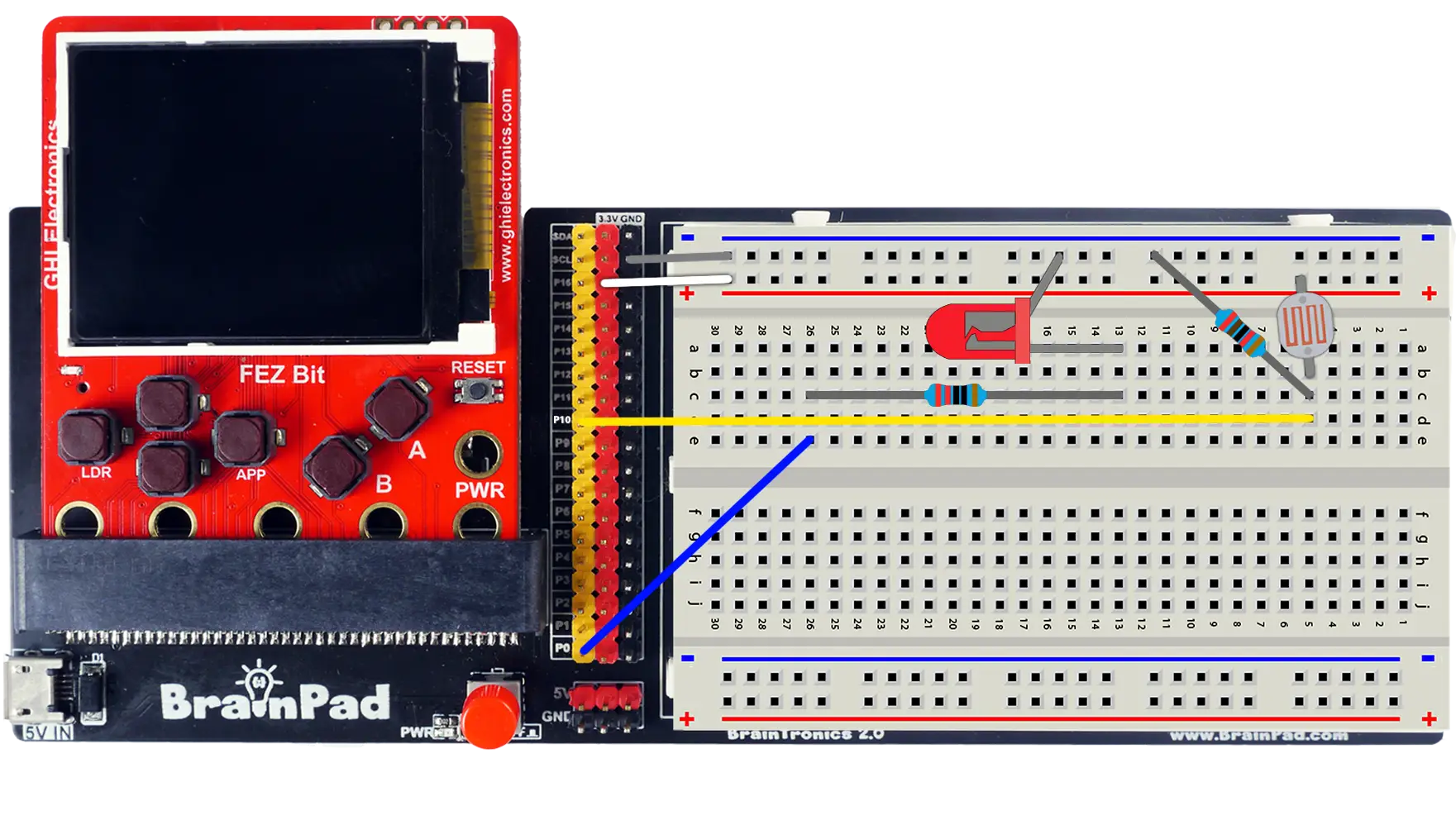
The display needs nothing. Rebuild the photoresistor divider from Light and Logic: photoresistor from the + rail to a row, 27 kΩ from that row to −, and that row to header pin P10.
Step 3 — Wake up the screen
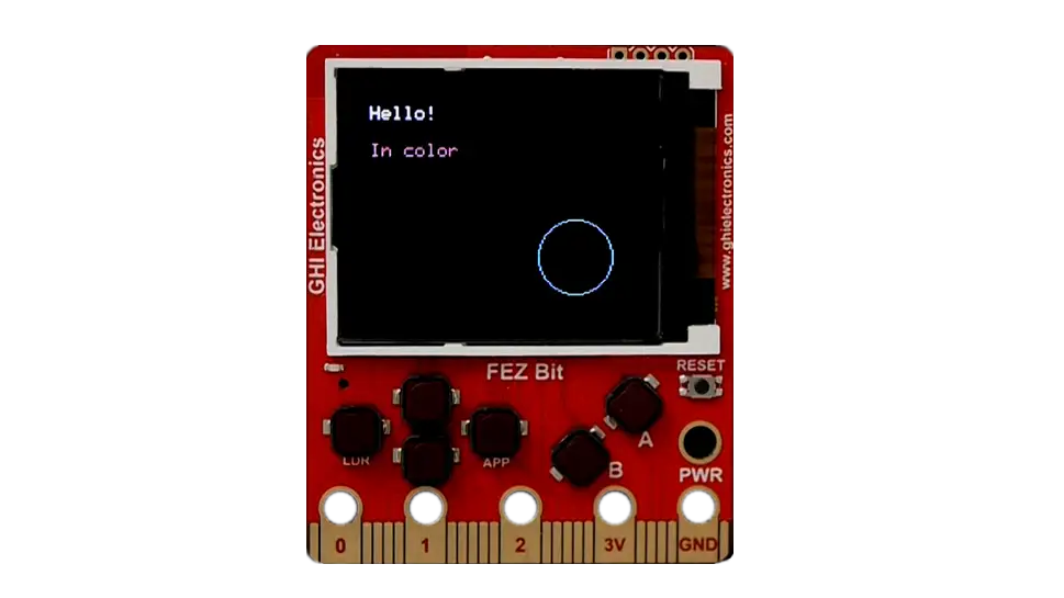
The display is an ST7735 on SPI. Four lines of setup, then it's ready:
using System.Threading;
using GHIElectronics.TinyCLR.Devices.Gpio;
using GHIElectronics.TinyCLR.Devices.Spi;
using GHIElectronics.TinyCLR.Drivers.BasicGraphics;
using GHIElectronics.TinyCLR.Drivers.Sitronix.ST7735;
using GHIElectronics.TinyCLR.Pins;

const int Width = 160;
const int Height = 128;

var gpio = GpioController.GetDefault();
var spi = SpiController.FromName(FEZBit.SpiBus.Display);

var display = new ST7735Controller(
    spi.GetDevice(ST7735Controller.GetConnectionSettings(
        SpiChipSelectType.Gpio,
        gpio.OpenPin(FEZBit.GpioPin.DisplayChipselect))),
    gpio.OpenPin(FEZBit.GpioPin.DisplayRs),
    gpio.OpenPin(FEZBit.GpioPin.DisplayReset));

// Backlight on — without it the screen draws but looks black.
var backlight = gpio.OpenPin(FEZBit.GpioPin.Backlight);
backlight.SetDriveMode(GpioPinDriveMode.Output);
backlight.Write(GpioPinValue.High);

display.SetDataAccessControl(true, true, false, false);     // orientation
display.SetDrawWindow(0, 0, Width - 1, Height - 1);
display.Enable();

var screen = new BasicGraphics(Width, Height, ColorFormat.Rgb565);

uint white = BasicGraphics.ColorFromRgb(255, 255, 255);
uint green = BasicGraphics.ColorFromRgb(0, 255, 0);
uint red = BasicGraphics.ColorFromRgb(255, 0, 0);

//Replace code below in Step 4

screen.Clear();
screen.DrawString("Hello!", white, 10, 10);
screen.DrawString("In color", green, 10, 30);
screen.DrawCircle(red, 120, 90, 20);

display.DrawBufferNative(screen.Buffer);

Thread.Sleep(Timeout.Infinite);
Press F5. White and green text and a red circle appear on the Bit's screen.
SetDataAccessControlsets which way round the image is drawn. If your text appears mirrored or upside down, flip the first two arguments.ColorFormat.Rgb565is 16 bits per pixel: 5 bits red, 6 green, 5 blue — 65,536 colors, and 2 bytes per pixel instead of 3.ColorFromRgbtakes ordinary 0–255 values and packs them for you.DrawBufferNativesends the whole image, the same as the OLED in Displays.
The buffer here is 160 × 128 × 2 = 40 KB, forty times the OLED's. Color costs memory, which is why the small chip in the FEZ Flea sticks to a monochrome screen.
Step 4 — A color readout

Color earns its place when it carries meaning. This readout turns from green to red as the room darkens:
var adc = AdcController.FromName(FEZBit.Adc.Controller1.Id);
var lightSensor = adc.OpenChannel(FEZBit.Adc.Controller1.P10);

while (true) {
    double light = ReadAverage(10);
    int percent = (int)(light * 100);

    // Dark rooms read red, bright rooms green.
    uint color = percent < 30 ? red : (percent < 60 ? BasicGraphics.ColorFromRgb(255, 200, 0) : green);

    screen.Clear();

    screen.DrawString("LIGHT LEVEL", white, 8, 8);
    screen.DrawString(percent + " %", color, 8, 32);

    // Bar, in the same color as the number.
    screen.DrawRectangle(white, 8, 70, 144, 16);
    for (int i = 0; i < percent * 140 / 100; i++) {
        screen.DrawLine(color, 10 + i, 72, 10 + i, 83);
    }

    display.DrawBufferNative(screen.Buffer);
    Thread.Sleep(100);
}

//Keep function below in Step 5

double ReadAverage(int samples) {
    double total = 0;

    for (int i = 0; i < samples; i++) {
        total += lightSensor.ReadRatio();
    }

    return total / samples;
}
Add using GHIElectronics.TinyCLR.Devices.Adc; at the top, replace everything after the screen.Clear() in Step 3, and press F5. Cup your hand over the sensor: the number, the bar, and their color all respond.
Try the debugger: set a breakpoint on display.DrawBufferNative(...) and hover over percent and color. The screen holds the last frame you sent while you look — exactly what you'd want when a readout shows something surprising.
Step 5 — A color graph
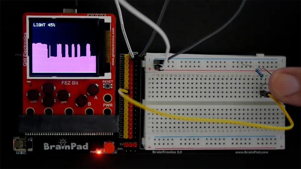
The same rolling history as the OLED lesson, with one advantage: each column can be colored by its own value, so a glance shows when the room was dark. Replace the while(true) loop from Step 4, but keep the ReadAverage() function below it.
int[] history = new int[Width];

while (true) {
    double light = ReadAverage(10);
    int percent = (int)(light * 100);

    for (int i = 0; i < Width - 1; i++) {
        history[i] = history[i + 1];
    }
    history[Width - 1] = percent;

    screen.Clear();
    screen.DrawString("LIGHT " + percent + "%", white, 4, 4);
    screen.DrawLine(white, 0, Height - 2, Width - 1, Height - 2);

    for (int i = 0; i < Width; i++) {
        int barHeight = history[i] * 90 / 100;
        uint columnColor = history[i] < 30 ? red : green;

        screen.DrawLine(columnColor, i, Height - 3, i, Height - 3 - barHeight);
    }

    display.DrawBufferNative(screen.Buffer);
    Thread.Sleep(100);
}
Press F5 and wave your hand slowly over the sensor. A red valley scrolls left every time the light drops — 16 seconds of history, readable across the room.
How it works
SPI, not I²C
The OLED in Displays used two wires and was slow enough for a small monochrome image. This screen has 40 KB to move per frame, so it uses SPI: a separate wire each way plus a clock, running much faster, with chip select picking the device instead of an address.
Two extra pins come along with it. RS (register select) tells the display whether the bytes arriving are a command or pixels, and Reset puts the controller in a known state at startup. The SPI page covers the bus itself.
Why the backlight is separate
An LCD makes no light of its own — it only blocks or passes the light behind it. That backlight is a plain LED panel on its own GPIO pin, which is why the screen looks black until you drive Backlight high. It's also PWM-capable, so FEZBit.Timer.Pwm.Controller2.Backlight can dim it the same way you dimmed an LED in Breathing LED.
The graphics engine
BasicGraphics is one of TinyCLR's two drawing libraries, and it works on every chip. The FEZ Bit's SC20100 also supports the graphics engine in GHIElectronics.TinyCLR.Drawing: Graphics, Bitmap, Pen, Brush, image decoding, and text in any font you embed.
The setup is the same display object, with the drawing surface coming from a bitmap instead:
// Requires the GHIElectronics.TinyCLR.Drawing NuGet package.
Graphics.OnFlushEvent += (sender, data, x, y, w, h, originalWidth) => display.DrawBufferNative(data);

var gfx = Graphics.FromImage(new Bitmap(Width, Height));

gfx.Clear();
gfx.FillEllipse(new SolidBrush(Color.Teal), 20, 20, 60, 40);
gfx.Flush();        // fires OnFlushEvent, which sends the buffer
What you gain: brushes, image files, and proper fonts. What it asks in return: text needs a font resource added to your project, since there's no built-in font — see Font Support and Resources. For readouts like this one, BasicGraphics' built-in font is simply less work.
The full picture is in Graphics, and the Create Graphics tutorial builds the same scene with both libraries.
What else is on the board
The FEZ Bit also has buttons A and B, four direction buttons, a buzzer, an accelerometer, and WiFi — all named in the pin library the same way the display is. The screen is what makes the rest of them worth using: a project can show what it's doing without a PC attached.
Try this
- Buttons and pages. Use
FEZBit.GpioPin.ButtonAandButtonBto switch between a light page and a distance page, using the Distance Sensor. - Dim the backlight. Drive
FEZBit.Timer.Pwm.Controller2.Backlightwith PWM, and dim the screen when the room is dark. - Big digits. Draw your own oversized numbers from filled rectangles — seven segments each — so the reading is readable from across the room.
- Radar plot. Put the distance sensor on the servo, sweep it, and draw each reading as a dot at the matching angle on screen. The Distance Sensor lesson explains the idea.
Next
Addressable LEDs: one wire, a whole strip of individually colored LEDs.
Something not working, or a step unclear? Ask in the TinyCLR forum — we read every post.