Analog Input

Every input so far has had two answers: pressed or not, high or low. The world isn't like that. Turn a knob and it passes through every position in between — and to read it, your board needs an ADC: an analog-to-digital converter that measures a voltage and hands your code a number.
This lesson is about the instrument. The next two lessons put it to work.
About 35 minutes.
What you'll learn
- What an ADC measures, and how a potentiometer produces a voltage to measure
- The difference between a ratio and a raw count, and what resolution means
- How to map a reading onto something useful, like LED brightness
- Why readings jitter, and how averaging steadies them
What you'll need
- From the kit:
- Rotary sensor (potentiometer)
- 1× LED and 1× 220 Ω resistor — the Digital Output circuit, wired again
- Jumper wires
Pin reference
| Connection | FEZ Flea | FEZ Bit |
|---|---|---|
| Potentiometer wiper (signal) | PA0 — ADC controller 1 | P4 — ADC controller 1 |
| Potentiometer ends | 3V3 and GND | 3.3V (adapter) and GND |
| LED (through the 220 Ω resistor) | PA3 | P0 |
Step 1 — Create the project
Create a new TinyCLR Application project and install GHIElectronics.TinyCLR.Devices.Adc, GHIElectronics.TinyCLR.Devices.Pwm, and GHIElectronics.TinyCLR.Pins.
Need the steps? Start Here covers creating a project and deploying.
GPIO and PWM had two APIs to choose from, and the lessons used the .NET IoT one. The ADC is TinyCLR-only — GHIElectronics.TinyCLR.Devices.Adc — so that's what this lesson uses. The shape is familiar: get a controller, open a channel.
Step 2 — Wire the potentiometer
A potentiometer has three connections: the two ends of a resistive track, and a wiper that slides along it as you turn the knob. Put 3.3 V across the ends, and the wiper delivers anything from 0 V to 3.3 V depending on its position.
With USB unplugged:
- FEZ Flea
- FEZ Bit
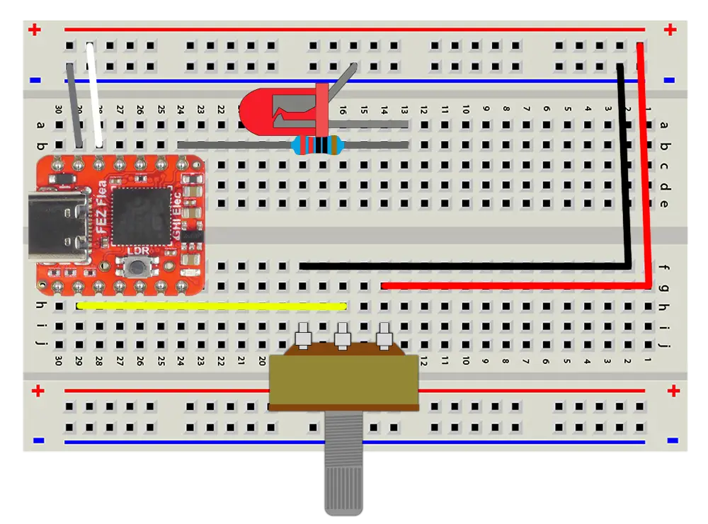
- Push the potentiometer into the breadboard, each pin in its own row.
- Connect one outer pin to the + rail, the other outer pin to the − rail.
- Connect the middle pin (the wiper) to PA0.
- Wire the LED and its 220 Ω resistor from PA3 to the − rail.
- Make sure the rails reach your board: 3V3 to +, GND to −.
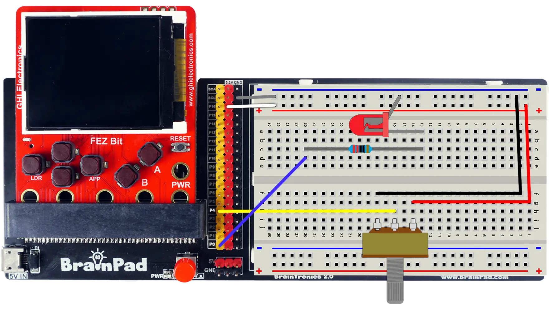
- Push the potentiometer into the breadboard, each pin in its own row.
- Connect one outer pin to the + rail, the other outer pin to the − rail.
- Connect the middle pin (the wiper) to header pin P4.
- Wire the LED and its 220 Ω resistor from header pin P0 to the − rail.
- Make sure the rails reach the adapter: 3.3V to +, GND to −.
Swapping the two outer pins isn't a mistake — it just reverses the knob, so clockwise counts down instead of up. If your readings run backwards, that's why.
Step 3 — Read the knob
ReadRatio() returns where the wiper sits, as a double from 0.0 (0 V) to 1.0 (3.3 V):
- FEZ Flea
- FEZ Bit
using System.Diagnostics;
using System.Threading;
using GHIElectronics.TinyCLR.Devices.Adc;
using GHIElectronics.TinyCLR.Pins;

var adc = AdcController.FromName(FEZFlea.Adc.Controller1.Id);
var knob = adc.OpenChannel(FEZFlea.Adc.Controller1.PA0);

while (true) {
    double ratio = knob.ReadRatio();

    Debug.WriteLine("Knob: " + ratio.ToString("N2"));
    Thread.Sleep(200);
}
using System.Diagnostics;
using System.Threading;
using GHIElectronics.TinyCLR.Devices.Adc;
using GHIElectronics.TinyCLR.Pins;

var adc = AdcController.FromName(FEZBit.Adc.Controller1.Id);
var knob = adc.OpenChannel(FEZBit.Adc.Controller1.P4);

while (true) {
    double ratio = knob.ReadRatio();

    Debug.WriteLine("Knob: " + ratio.ToString("N2"));
    Thread.Sleep(200);
}
Press F5 and turn the knob. The Output window streams the value: 0.00 at one end, 1.00 at the other, everything in between on the way.
Try the debugger: set a breakpoint on Debug.WriteLine(...). Turn the knob a little, press F5, and look at the Locals window — ratio shows exactly what the wiper was at the instant the code ran. Keep pressing F5 while turning: each stop is a fresh measurement of the real voltage on the pin.
Step 4 — Ratios and raw counts
ReadRatio is doing a conversion for you. The ADC's actual output is a whole number of counts. Add it to the loop:
double ratio = knob.ReadRatio();
int raw = knob.ReadValue();

Debug.WriteLine("Knob: " + ratio.ToString("N2") + "   raw: " + raw);
Run it and turn the knob all the way to each end. The largest raw number depends on your board:
- FEZ Flea
- FEZ Bit
The FEZ Flea's ADC is 12-bit: 2¹² = 4096 steps, so raw values run from 0 to 4095. Each step is about 3.3 V ÷ 4096 ≈ 0.8 mV.
The FEZ Bit's ADC is 16-bit: 2¹⁶ = 65,536 steps, so raw values run from 0 to 65,535. Each step is about 3.3 V ÷ 65,536 ≈ 0.05 mV.
That's why the lessons use ReadRatio: 0.0 to 1.0 means the same thing on every board, while raw counts don't. Reach for ReadValue when you need the exact number of steps, or the last bit of precision.
To convert a ratio into volts, multiply by the supply voltage:
double volts = ratio * 3.3;
Step 5 — Dim the LED with the knob
A reading is only useful once it controls something. Feed the knob straight into the PWM duty cycle from Breathing LED:
- FEZ Flea
- FEZ Bit
using System.Device.Pwm;
using System.Diagnostics;
using System.Threading;
using GHIElectronics.TinyCLR.Devices.Adc;
using GHIElectronics.TinyCLR.Pins;

var adc = AdcController.FromName(FEZFlea.Adc.Controller1.Id);
var knob = adc.OpenChannel(FEZFlea.Adc.Controller1.PA0);

using PwmChannel led = PwmChannel.Create(
    FEZFlea.Timer.Pwm.Controller15.Chip,
    FEZFlea.Timer.Pwm.Controller15.PA3,
    1000,
    0);

led.Start();

while (true) {
    double ratio = knob.ReadRatio();

    led.DutyCycle = ratio * ratio;      // the brightness curve from Breathing LED
    Debug.WriteLine("Knob: " + ratio.ToString("N2"));

    Thread.Sleep(20);
}
using System.Device.Pwm;
using System.Diagnostics;
using System.Threading;
using GHIElectronics.TinyCLR.Devices.Adc;
using GHIElectronics.TinyCLR.Pins;

var adc = AdcController.FromName(FEZBit.Adc.Controller1.Id);
var knob = adc.OpenChannel(FEZBit.Adc.Controller1.P4);

using PwmChannel led = PwmChannel.Create(
    FEZBit.Timer.Pwm.Controller3.Chip,
    FEZBit.Timer.Pwm.Controller3.P0,
    1000,
    0);

led.Start();

while (true) {
    double ratio = knob.ReadRatio();

    led.DutyCycle = ratio * ratio;      // the brightness curve from Breathing LED
    Debug.WriteLine("Knob: " + ratio.ToString("N2"));

    Thread.Sleep(20);
}
Press F5 and turn the knob. The LED follows your hand — a dimmer you built.
Reading 50 times a second is smooth to the eye and leaves the processor idle most of the time. Values from 0.0 to 1.0 drop straight into the duty cycle, which is exactly why a ratio is a convenient shape to read in.
Step 6 — Steady the reading
Leave the knob alone and watch the Output window. The last digits probably still twitch — 0.47, 0.48, 0.47. Nothing is broken: the ADC is measuring real, tiny fluctuations from the power supply, nearby wires, and the converter itself.
When a small wobble matters, take several readings and average them:
double ReadAverage(int samples) {
    double total = 0;

    for (int i = 0; i < samples; i++) {
        total += knob.ReadRatio();
    }

    return total / samples;
}
Call ReadAverage(10) instead of knob.ReadRatio(). The reading settles down, at the cost of ten conversions instead of one — which still takes well under a millisecond.
Averaging is the first tool to reach for whenever a sensor reading is noisy, and it comes back in the next lesson.
How it works
What the ADC does
The ADC compares the voltage on the pin against the board's reference voltage — 3.3 V here — and reports the result as a fraction of it, in whole steps.
3.3 V  ─────────────────── 1.00  (4095 counts on the Flea, 65535 on the Bit)
2.5 V  ─────────────────── 0.76
1.65 V ─────────────────── 0.50
0.8 V  ─────────────────── 0.24
0 V    ─────────────────── 0.00
It measures voltage, never current or resistance. Any sensor you want to read has to produce a voltage first — which is exactly what the potentiometer does.
The potentiometer is a voltage divider
Inside is a resistive track with the wiper touching it somewhere along its length. That splits the track into two resistors in series, and the wiper sits at the junction:
3.3V ──┬──────────┐
       │          │
      [R top]     │   turning the knob moves the wiper,
       │          │   changing how much of the track is
       ├───────── wiper ──→ to the ADC pin
       │          │   above it and how much below
      [R bottom]  │
       │          │
GND ───┴──────────┘
Turn the wiper to the top and it reads nearly 3.3 V; to the bottom, nearly 0 V; halfway, about 1.65 V. The ratio of the two resistances sets the voltage, which is why a voltage divider is the standard way to turn a varying resistance into something an ADC can read. The next lesson builds one by hand, with a light sensor in place of the track.
Resolution
Resolution is how finely the ADC can slice the range. More bits means smaller steps:
| ADC | Steps | Step size at 3.3 V |
|---|---|---|
| 12-bit (FEZ Flea) | 4,096 | ~0.8 mV |
| 16-bit (FEZ Bit) | 65,536 | ~0.05 mV |
A change smaller than one step doesn't register at all. More resolution also means the noise in Step 6 shows up in more digits — precision and steadiness are not the same thing.
For high-impedance sensors that need longer to settle, and the sampling-time settings that give them that time, see Analog In.
Try this
- Knob to servo. Rewire the servo from Servo Motor and drive its angle with the knob:
SetAngle(ratio * 180). Turn the knob, and the arm follows. - Knob to pitch. Map the knob onto the buzzer's frequency from Sound — say 200 Hz to 2000 Hz — for a one-string instrument.
- Knob to color. Bring back the RGB module and use the knob to travel around the color wheel from RGB LEDs.
- Volume meter. Light the LED only above a knob position you choose, and print "over" or "under" when it crosses. Watch how it behaves right at the edge: that flicker is the problem the next lesson solves.
Next
Light and Logic: a sensor whose readings depend on the room, and how to turn messy numbers into a reliable decision.
Something not working, or a step unclear? Ask in the TinyCLR forum — we read every post.