Addressable LEDs
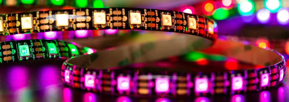
The RGB module in RGB LEDs took three pins to make one color. Addressable LEDs take one pin — and give you a whole strip, each LED its own color. Every one of them has a tiny controller built in, listening for its own slice of a message that travels down the line.
They're everywhere: strips, rings, matrices, and the glow in the back of half the products on a store shelf.
About 35 minutes.
This lesson needs a WS2812 (NeoPixel) strip, ring, or stick, from any electronics supplier. Start with a small one — 8 LEDs or fewer — for the power reasons in Step 2.
What you'll learn
- How a single data wire controls dozens of individually colored LEDs
- How to set, animate, and send colors from C#
- How to work out a power budget, and why brightness costs current
- Why these LEDs run from 3.3 V in this lesson, rather than the usual 5 V
What you'll need
- A WS2812 / NeoPixel strip or ring (8 LEDs or fewer to start)
- Jumper wires — pin-to-socket wires suit most strips' loose leads
Pin reference
| Strip wire | FEZ Flea | FEZ Bit |
|---|---|---|
| DIN (data in) | PA3 | P0 |
| 5V / VCC | 3V3 | 3.3V (adapter) |
| GND | GND | GND |
Any GPIO pin can drive these LEDs — the driver generates the timing itself. PA3 and P0 are just the pins your first LED used.
Step 1 — Create the project
Create a new TinyCLR Application project and install GHIElectronics.TinyCLR.Drivers.Worldsemi.WS2812, GHIElectronics.TinyCLR.Devices.Gpio, and GHIElectronics.TinyCLR.Pins.
Need the steps? Start Here covers creating a project and deploying.
Like the Distance Sensor, this lesson uses TinyCLR's own GPIO API, because the driver takes its pin in that form.
Step 2 — Wire the strip
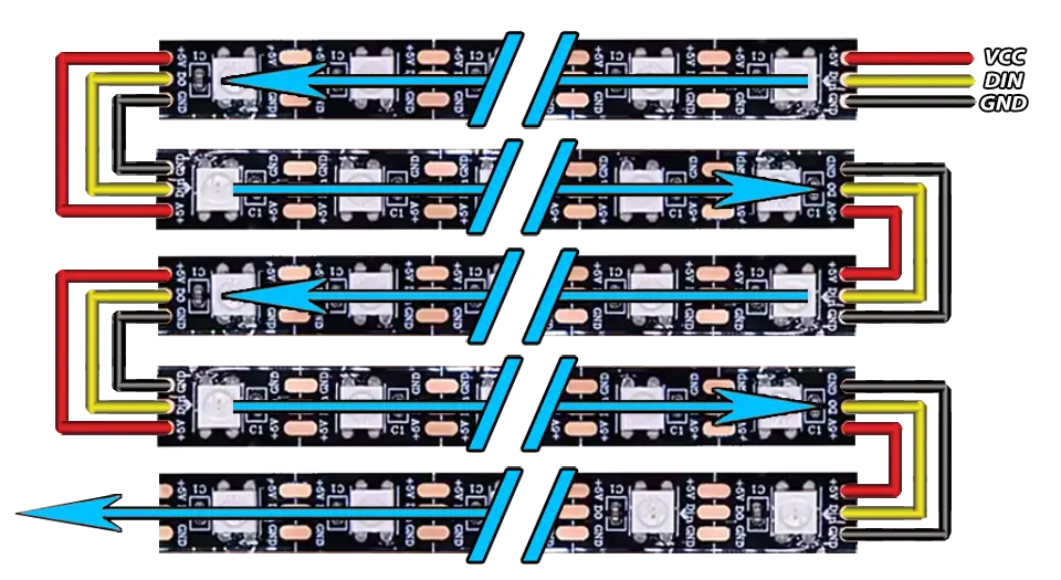
A strip has three connections: power, ground, and data in. Strips also have a data out at the far end, for chaining more — leave it unconnected.
With USB unplugged:
- FEZ Flea
- FEZ Bit
- VCC (often labeled 5V) → the + rail, which is 3.3 V.
- GND → the − rail.
- DIN → PA3. Check the arrows printed on the strip: data flows into the end you connect.
- VCC (often labeled 5V) → the + rail, which is 3.3 V.
- GND → the − rail.
- DIN → header pin P0. Check the arrows printed on the strip: data flows into the end you connect.
Power the strip from 3.3 V for this lesson, not 5 V, and keep it to a handful of LEDs.
Two reasons. A WS2812 expects its data signal to be close to its own supply voltage, so a 5 V strip driven by a 3.3 V pin is out of specification — it often works, then fails on a different strip or in a warmer room. And at full white, each LED can draw about 60 mA: eight of them is nearly half an amp, far more than a board's regulator or a USB port wants to give.
At 3.3 V with a few LEDs, both problems go away. To drive a long strip properly, give it its own 5 V supply and a level shifter on the data line.
Step 3 — Light one LED
- FEZ Flea
- FEZ Bit
using System.Threading;
using GHIElectronics.TinyCLR.Devices.Gpio;
using GHIElectronics.TinyCLR.Drivers.Worldsemi.WS2812;
using GHIElectronics.TinyCLR.Pins;

const int LedCount = 8;                 // however many your strip has

var dataPin = GpioController.GetDefault().OpenPin(FEZFlea.GpioPin.PA3);

var strip = new WS2812Controller(dataPin, LedCount, WS2812Controller.DataFormat.rgb888);

strip.SetColor(0, 0x20, 0, 0);          // first LED, dim red
strip.Flush();

Thread.Sleep(Timeout.Infinite);
using System.Threading;
using GHIElectronics.TinyCLR.Devices.Gpio;
using GHIElectronics.TinyCLR.Drivers.Worldsemi.WS2812;
using GHIElectronics.TinyCLR.Pins;

const int LedCount = 8;                 // however many your strip has

var dataPin = GpioController.GetDefault().OpenPin(FEZBit.GpioPin.P0);

var strip = new WS2812Controller(dataPin, LedCount, WS2812Controller.DataFormat.rgb888);

strip.SetColor(0, 0x20, 0, 0);          // first LED, dim red
strip.Flush();

Thread.Sleep(Timeout.Infinite);
Press F5. The first LED glows dim red.
SetColor(index, red, green, blue)sets one LED in memory. Index 0 is the one nearest the data-in end.Flush()sends the whole set down the wire. Nothing changes on the strip until you call it.0x20instead of0xFF. That's about 12% brightness — plenty indoors, and far kinder to your power budget and your eyes. Try0xFFonce to see the difference, then turn it back down.
Nothing lit? Check the data arrow on the strip, and that its ground shares the − rail with your board.
Step 4 — Color every LED
Set them all, then push one update:
// Eight colors around the wheel, at low brightness.
byte[] red   = { 0x20, 0x20, 0x20, 0x00, 0x00, 0x00, 0x20, 0x20 };
byte[] green = { 0x00, 0x10, 0x20, 0x20, 0x20, 0x00, 0x00, 0x10 };
byte[] blue  = { 0x00, 0x00, 0x00, 0x00, 0x20, 0x20, 0x20, 0x10 };

for (int i = 0; i < LedCount; i++) {
    strip.SetColor(i, red[i], green[i], blue[i]);
}

strip.Flush();
Same column layout as the colors in RGB LEDs — one column per LED this time instead of one per moment.
Step 5 — Animate
An animation is just a loop that changes the colors and flushes again. This one chases a single dot along the strip and back:
int position = 0;
int direction = 1;

while (true) {
    // Clear every LED, then light one.
    for (int i = 0; i < LedCount; i++) {
        strip.SetColor(i, 0, 0, 0);
    }

    strip.SetColor(position, 0, 0x20, 0x20);
    strip.Flush();

    position += direction;

    if (position == LedCount - 1 || position == 0) {
        direction = -direction;         // bounce off the end
    }

    Thread.Sleep(80);
}
Press F5. A dot bounces from end to end.
Try the debugger: set a breakpoint on strip.Flush(); and press F5 repeatedly. The strip advances one frame per press, and position in the Locals window tells you which LED is about to light. Animations are much easier to debug one frame at a time.
Step 6 — Fade the tail
Instead of clearing every LED each frame, dim them. Whatever was bright a moment ago fades out behind the dot, and a comet trail appears — for very little code.
Keep arrays of the current color and scale them each frame:
byte[] level = new byte[LedCount];
int position = 0;
int direction = 1;

while (true) {
    for (int i = 0; i < LedCount; i++) {
        level[i] = (byte)(level[i] * 3 / 4);        // fade to 75% each frame
    }

    level[position] = 0x30;                          // the head of the comet

    for (int i = 0; i < LedCount; i++) {
        strip.SetColor(i, 0, level[i], (byte)(level[i] / 2));
    }

    strip.Flush();

    position += direction;
    if (position == LedCount - 1 || position == 0) {
        direction = -direction;
    }

    Thread.Sleep(60);
}
Change 3 / 4 to 9 / 10 for a longer tail, or 1 / 2 for a short one.
How it works
One wire, many LEDs
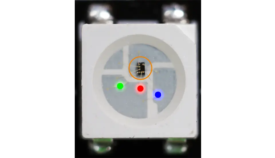
Each LED contains a small controller. When a message arrives at its data-in pin, it keeps the first set of color values for itself and passes the rest out its data-out pin to the next LED. So a strip of eight needs a message with eight colors, and each LED quietly takes its own.
board ──→ [LED 0] ──→ [LED 1] ──→ [LED 2] ──→ …
          keeps 1st    keeps 2nd    keeps 3rd
That's why Flush() matters. SetColor only edits a buffer in memory; Flush transmits the whole thing.
Why timing is the hard part
There's no clock wire. A bit is encoded in the length of a high pulse — roughly 0.4 µs for a 0 and 0.8 µs for a 1, with a tolerance of about 150 nanoseconds. Miss that window and colors come out wrong or the strip flickers.
No managed language can hit that reliably by toggling a pin in a loop, which is why TinyCLR's WS2812 driver generates the waveform natively. From C#, you set colors and call Flush — the strict timing is handled below you. This is the same reason the Distance Sensor used PulseFeedback instead of timing an echo by hand.
The power budget
Each LED has three chips inside, one per color, drawing roughly 20 mA each at full brightness. White at full power is therefore about 60 mA per LED:
| LEDs | Full white | At 0x20 (about 12%) |
|---|---|---|
| 8 | ~480 mA | ~60 mA |
| 30 | ~1.8 A | ~220 mA |
| 144 | ~8.6 A | ~1 A |
A USB port supplies 500 mA in total, and your board needs some of that. Two consequences worth remembering: keep brightness low unless you have a real power supply, and treat any strip longer than a few LEDs as something that needs its own supply, wired to the strip directly rather than through your board.
Color depth
DataFormat.rgb888 sends eight bits per color — 16.7 million combinations. The driver also supports rgb565, which packs a color into two bytes instead of three: fewer shades, but a third less data to send, which matters on a long strip being animated quickly.
Try this
- Rainbow. Fade around the color wheel from RGB LEDs, with each LED a step further along the wheel than its neighbor. Move the whole pattern one step per frame.
- Knob-controlled brightness. Bring back the potentiometer from Analog Input and scale every color by the knob position.
- Level meter. Use the photoresistor from Light and Logic: the brighter the room, the more LEDs light up.
- Distance bar. Light more LEDs the closer something gets, using the Distance Sensor — a parking sensor you can see instead of hear.
- Go bigger. A WS2812 matrix can be wrapped in a class and drawn on with BasicGraphics, text and shapes included. See Extended Features → LEDs for a matrix example, and the APA102C and LPD8806 drivers for SPI-based strips.
Next
You've reached the end of the current lessons. From here, the whole world of inexpensive modules is open: Start Here lists the follow-on guides, and Limitations is worth a skim before you build something of your own.
Something not working, or a step unclear? Ask in the TinyCLR forum — we read every post.