Electronics Lab for the .NET Developer
Project-based lessons that take you from blinking an LED to buttons, sound, servo control, analog sensing, and ultrasonic distance measurement — all in C#, with the Visual Studio debugger attached to real hardware. Set a breakpoint and the board stops with it. Hover a variable to read a sensor.
If you can write a loop and a method, you're ready. No electronics background needed, no soldering, no new IDE.
This page covers everything you need before the first lesson: setting up your PC, getting to know your board, and the wiring basics every lesson builds on. Already comfortable with breadboards? Skim your board's pins and jump straight in.
Post in the TinyCLR forum — the people who write the runtime and ship the kits read and answer there. Tell us your board, which lesson, and what you saw; a photo of your wiring helps.
Choose your board
Every lesson works on both lab boards — the wiring and the code are the same except for pin names:
- FEZ Flea — stamp-sized, plugs straight into the breadboard.
- FEZ Bit — adds a 1.8" color display, WiFi, and on-board buttons and buzzer. Plugs into an adapter board next to the breadboard.
Wherever the two differ, lessons show a FEZ Flea / FEZ Bit switch like the one below. Pick your board once — every page remembers it.
- FEZ Flea
- FEZ Bit
You're following along with the FEZ Flea. Pin names look like PA3, and in code FEZFlea.GpioPin.PA3.
You're following along with the FEZ Bit. Pin names look like P0, and in code FEZBit.GpioPin.P0.
What's in the kit
- FEZ Flea
- FEZ Bit
- FEZ Flea — running TinyCLR, with headers fitted
- Solderless breadboard
- USB-C cable
- FEZ Bit — running TinyCLR, with a 1.8" color display and WiFi
- Solderless breadboard with a FEZ Bit adapter board
- USB-C cable — for the FEZ Bit
- Micro USB cable — for powering the adapter board
Both kits include the same parts:
- HC-SR04 ultrasonic distance sensor
- Analog joystick (2-axis + button)
- Color (RGB) LED module
- Positional servo motor
- Rotary sensor (potentiometer)
- 4× colored pushbuttons
- Piezo buzzer
- Light sensor (photoresistor)
- 6× LEDs
- 10× 220 Ω resistors — for LEDs
- 5× 27 kΩ resistors — for pull-ups and pull-downs
- 10× pin-to-pin (male-to-male) jumper wires
- 10× pin-to-socket (male-to-female) jumper wires
- Zippered case
Set up and blink
Five minutes, and you've proved your PC, your board, and the tools all work together. This is also the exact workflow every lesson uses.
These lessons teach electronics, not C# or .NET setup. Before starting, your PC should already build and run a plain C# "hello world", and you should be comfortable adding NuGet packages to a project — every lesson begins by installing a couple.
In Visual Studio that means the .NET desktop development workload is installed. In VS Code it means a .NET SDK, installed directly or by an extension that brings it along. If a hello world builds and runs, the TinyCLR tooling has what it needs.
- Install Visual Studio 2026 — any edition, including the free Community Edition — with the .NET desktop development workload.
- Install the TinyCLR extension.
Extensions→Manage Extensions…, search fortinyclr, install TinyCLR OS Project, restart Visual Studio. - Create a project.
Create a new project→ pick TinyCLROS from the Platforms dropdown → TinyCLR Application → name it and click Create. - Install the NuGet packages. Right-click the project →
Manage NuGet Packages…→ Browse, then addGHIElectronics.TinyCLR.Devices.GpioandGHIElectronics.TinyCLR.Pins. Each lesson lists the packages it needs in Step 1. - Plug your board into USB and replace
Program.cswith:
- FEZ Flea
- FEZ Bit
using System.Device.Gpio;
using System.Threading;
using GHIElectronics.TinyCLR.Pins;

using GpioController controller = new GpioController();

int ledPin = FEZFlea.GpioPin.Led;
controller.OpenPin(ledPin, PinMode.Output);

while (true) {
    controller.Write(ledPin, PinValue.High);
    Thread.Sleep(500);

    controller.Write(ledPin, PinValue.Low);
    Thread.Sleep(500);
}
using System.Device.Gpio;
using System.Threading;
using GHIElectronics.TinyCLR.Pins;

using GpioController controller = new GpioController();

int ledPin = FEZBit.GpioPin.Led;
controller.OpenPin(ledPin, PinMode.Output);

while (true) {
    controller.Write(ledPin, PinValue.High);
    Thread.Sleep(500);

    controller.Write(ledPin, PinValue.Low);
    Thread.Sleep(500);
}
- Press F5. Visual Studio builds, finds your board, deploys, and attaches the debugger — and the on-board LED blinks.
That's it. Every lesson from here is the same four moves: new project, add packages, paste code, press F5.
If the Output window shows something like this:
Error: the reference mscorlib cannot be used with this version of the firmware.
Firmware checksum 0x8FF20F1B does not match the assembly checksum 0x04F4012C.
your board's firmware is older than the NuGet packages you just installed. Install or update firmware sorts it out in a couple of minutes. Otherwise there's nothing to do — kits ship ready to run.
TinyCLR development requires Windows. The lessons use Visual Studio for screenshots and shortcuts; VS Code works too, with its own project type. The C# is identical either way, and so are F5, F10, and F11.
Want the full walkthrough, including what the bootloader and firmware actually do? TinyCLR Getting Started.
Get to know your board
Each pin has a name you use in code, and a set of functions that tell you what else it can do. Lessons tell you which pin to use — this is the map to find it.
| Function | What it does | First used in |
|---|---|---|
| GPIO | Digital input or output. Every signal pin can do this. | Digital Output |
| PWM | Generates pulses — for dimming LEDs, mixing colors, making tones, and driving servos. | Breathing LED |
| ADC | Reads an analog voltage — for knobs, light sensors, and joysticks. | Analog Input |
| I²C, SPI | Buses for displays and sensors. | Displays |
| 3.3V, 5V | Power for the parts on your breadboard. | Analog Input |
| GND | Ground — the 0 V reference every circuit returns to. | Digital Output |
- FEZ Flea
- FEZ Bit
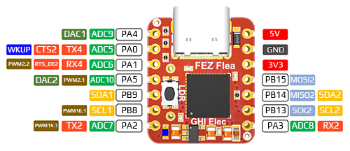
The white boxes are pin names (PA3 → FEZFlea.GpioPin.PA3 in code); the colored labels are functions.
| Function | FEZ Flea pins |
|---|---|
| GPIO | PA0, PA1, PA2, PA3, PA4, PA5, PB8, PB9, PB13, PB14, PB15 |
| PWM | PA1, PA2, PA3, PA5, PB8 |
| ADC | PA0, PA1, PA2, PA3, PA4, PA5 |
| I²C | PB9 (SDA), PB8 (SCL) |
| SPI | PB15 (MOSI), PB14 (MISO), PB13 (SCK) |
| Power | 3V3, 5V, GND |
On the board: a user LED (FEZFlea.GpioPin.Led) — the one you blinked in Getting Started — and an LDR button for loading firmware.
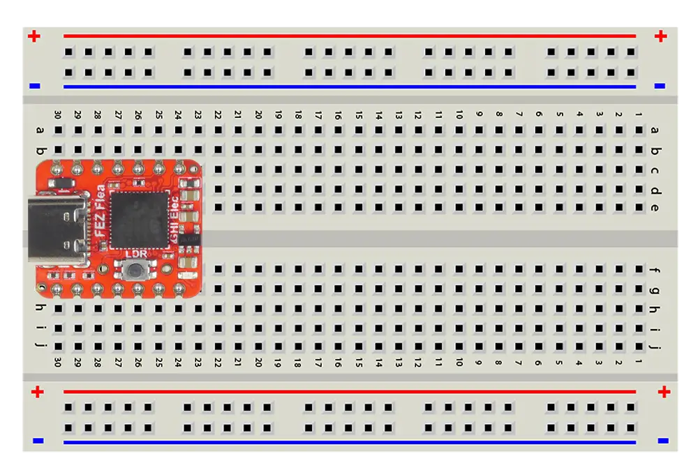
Setting up: push the Flea into the breadboard so it straddles the center gap — its two rows of pins on opposite halves. That way every pin gets its own row, and no two pins are shorted together. Parts connect by sharing a row with a pin, or with a pin-to-pin jumper wire.
Power: the single USB-C cable does everything — loads your code and powers the board. The Flea's 3V3 and 5V pins power the parts on your breadboard.
Full specs and the schematic: FEZ Flea.

Pins on the edge connector are named P0–P16 (P0 → FEZBit.GpioPin.P0 in code).
| Function | FEZ Bit pins |
|---|---|
| GPIO | P0–P16 |
| PWM | P0, P1, P2, P3, P14, P15 |
| ADC | P0, P1, P2, P3, P4, P9, P10, P13, P14, P15 |
| I²C | P20 (SDA), P19 (SCL) |
| SPI | P15 (MOSI), P14 (MISO), P13 (SCK) |
| Power (adapter board) | 5V, 3.3V, GND |
On the board: a user LED (FEZBit.GpioPin.Led), a buzzer (FEZBit.GpioPin.Buzzer), buttons A and B plus four direction buttons, a 1.8" color display, and WiFi. The lessons use the breadboard parts so they match the Flea — but you're free to try the on-board versions too.
Setting up: slide the FEZ Bit into the adapter board's edge connector, display facing up. The adapter brings every pad on the FEZ Bit out to a row of male header pins next to the breadboard. Connect a header pin to a breadboard row with a pin-to-socket (male-to-female) jumper wire — the socket end goes on the header pin.
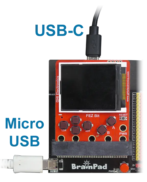
Power: the FEZ Bit kit uses two USB cables:
- USB-C → FEZ Bit — loads and debugs your code.
- Micro USB → adapter board — powers the adapter's regulator, which provides 5V and 3.3V on the header for the parts on your breadboard. It powers the FEZ Bit too.
While you're coding, plug in both. When you're done, unplug the USB-C cable — the adapter's micro USB cable alone keeps your project running.
Power breadboard parts from the adapter's 5V and 3.3V pins, not the FEZ Bit's own 3V pad. The FEZ Bit's regulator is sized for the board itself; the adapter's regulator is there for your circuits.
Full specs and the schematic: FEZ Bit.
How a breadboard works

A breadboard lets you build circuits by pushing parts and wires into holes — no soldering. Inside, metal strips connect certain holes together:
- Rows of five. Each short row of five holes (for example,
a–ein row 10) is connected. Anything plugged into the same row is wired together. - The center gap. The channel down the middle separates the two halves. Row 10
a–eis not connected to row 10f–j.
- Power rails. The long strips along the edges, marked + (red) and − (blue), run the length of the board. Connect them to 3.3V and GND once and every part can reach power from anywhere.

On some breadboards the power rails are split in the middle — a gap in the red and blue lines is the giveaway. Bridge the halves with a short jumper if you need power along the full length.
Jumper wires
- Pin-to-pin (male-to-male) — for connecting holes on the breadboard to each other.
- Pin-to-socket (male-to-female) — for modules with header pins, like the distance sensor, joystick, and servo — and for the FEZ Bit adapter's header pins.
Wire color doesn't affect the circuit, but a habit makes circuits easier to check: red for power, black for GND, other colors for signals.
Parts you'll meet first
LEDs
An LED only lights when current flows in one direction:
- The longer leg is the anode (+). It connects toward the pin.
- The shorter leg — next to the flat edge of the LED's rim — is the cathode (−). It connects toward GND.
Put one in backwards and it simply stays dark — no harm done. Flip it around.
Resistors
Resistors limit current, and they have no polarity — either direction works, so you can't put one in backwards. The kit has two values:
| Value | Used for | On the paper strip | 5-band code | 4-band code |
|---|---|---|---|---|
| 220 Ω | Every LED — 10 in the kit | 220R | red · red · black · black · brown | red · red · brown · gold |
| 27 kΩ | Pull-ups and pull-downs — 5 in the kit | 27K | red · violet · black · red · brown | red · violet · orange · gold |
Two things trip people up the first time:
220Rmeans 220 Ω. The letter sits where the decimal point would go, which keeps a smudged dot from changing the value. So4K7is 4.7 kΩ, and1M0is 1 MΩ.- Your resistors have five bands, not four. Most charts online show four. With five, the first three bands are digits instead of two, the fourth is the multiplier, and the last is tolerance — a brown final band means ±1%. Both codes are in the table above, so you can match whichever chart you find.
The easiest approach: leave them on the labeled strip until you need one. Each lesson says which value to use and why.
Wiring habits
These five habits prevent almost every beginner mistake:
- Unplug USB while wiring — both cables on the FEZ Bit. Plug back in when the circuit is complete.
- Never connect 3.3V or 5V directly to GND. That's a short circuit.
- Never connect two pins that are both outputs. If one drives high and the other low, the chip can be damaged.
- Always use a resistor with an LED. Digital Output explains why.
- Check your wiring against the lesson before powering up. Most "my code doesn't work" moments are one wire in the wrong row.
Signal pins run at 3.3 V and can supply only a few milliamps — enough for LEDs and signals, not for motors or bright lamps. Parts that need more, like the servo, get their power from the 5V pin, and that lesson shows how.
The lessons
Work through them in order — each one builds on the last:
-
Digital Output — control your first LED, understand current-limiting resistors
-
Digital Input — buttons and pull-up resistors — the kit's 27 kΩ resistors first, then the chip's built-in ones — plus events and a multi-button reaction-time game
-
Breathing LED — control power level with pulse-width modulation
-
RGB LEDs — mix colors, first with digital outputs, then with PWM for any color
-
Sound — frequency, pitch, and a melody on a piezo buzzer
-
Servo Motor — positioning with pulses
-
Analog Input — the potentiometer as a dimmer; watch the ADC live in the debugger
-
Light and Logic — a photoresistor night-light with hysteresis
-
Joystick — a fun project: steer the servo or mix RGB colors with your thumb
-
Distance Sensor — measure distance with ultrasound, and see why a radar is just a distance sensor that moves
-
Displays — add a small I²C OLED: text, shapes, a live readout, and a scrolling graph
-
FEZ Bit Screen — the same readout in color on the FEZ Bit's built-in display, with nothing to wire
-
Addressable LEDs — WS2812 / NeoPixel strips: color, brightness, and animation from C#
The last three need a part beyond the kit, except FEZ Bit Screen, which uses the display already on the board — each lesson lists exactly what to get.
Every lesson has a wiring photo, a schematic, and copy-paste C# code. And because your board runs with the debugger attached, breakpoints and variable inspection work everywhere — lessons point out the spots worth a look.
After the lessons
Everything in this lab uses standard breadboard parts, so the skills carry over to any module you can buy — and TinyCLR ships drivers for a lot of them. Two popular next steps:
- LED matrices — scrolling text, simple graphics, and your first animation loop, built on the WS2812 driver from Addressable LEDs
- Common sensors — temperature, humidity, pressure, and accelerometers over I²C and SPI, in Extended Features → Sensors
Extended Features is the full catalog: displays, codecs, connectivity, motors, memory, and more, each with example code.
Before building your own project, skim Limitations — a short list of full-.NET features TinyCLR trims to fit on a microcontroller. None of them come up in the lessons.