Signal Control
Signal Control covers a family of APIs for working with digital pins at the timing level — generating precise waveforms, measuring pulse widths, and reading sensors that communicate by timing edges (ultrasonic rangefinders, capacitive touch surfaces, IR receivers).
NuGet packages: GHIElectronics.TinyCLR.Devices.Signals for the API, and GHIElectronics.TinyCLR.Pins for pin name constants.
DigitalSignal
DigitalSignal is the hardware-backed signal API — accurate, non-blocking, no CPU overhead. Because it's hardware-backed, it only runs on specific Timer-capable pins, found under SC20260.Timer.DigitalSignal.Controller?.xxx.
Timers are also used with other features like PWM. Once a Timer is reserved for DigitalSignal, it's no longer available to other features that need the same Timer.
Two roles: generating an outgoing signal, or capturing an incoming one. Capture supports both a raw stream of edge durations (signal analyzer) and a pulse counter (ReadPulse).
Generate
Generate creates a precise output signal driven entirely by hardware. Each value in the data array is the length of one pulse (high or low) in ticks. By default one tick is 100 ns.
Generate(uint[] data, uint offset, uint count)
Limits on data:
- Max 64K elements per array.
- The sum of all element values must not exceed
0xFFFFFFFFticks.
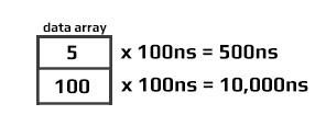
Generate(uint[] data, uint offset, uint count, uint multiplier)
The multiplier scales each tick to a custom time unit. The allowed range depends on the chip family.
SC20xxx — multiplier from 25 to 250,000 (250 µs). The multiplier must satisfy two divisibility rules:
- 1,000,000,000 must be evenly divisible by the multiplier.
- 240,000,000 must be evenly divisible by (1,000,000,000 ÷ multiplier).
The clock source is always 240 MHz, so full and half speed behave identically.
SC13xxx (full speed) — multiplier from 25 to 800,000 (800 µs). Same two rules, but the clock source is 80 MHz:
- 1,000,000,000 must be evenly divisible by the multiplier.
- 80,000,000 must be evenly divisible by (1,000,000,000 ÷ multiplier).
SC13xxx (half speed) — the clock drops to 40 MHz and the multiplier range extends to 25 to 1,600,000 (1.6 ms).
The generator starts at low, then toggles every time a value from the array elapses. Sending an even number of pulses leaves the signal high at the end:
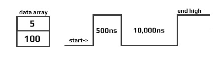
The next Generate call always starts by driving low — which inserts an extra pulse with variable width if the previous signal ended high. To leave the line resting low at the end (avoiding that extra pulse), make sure the data length is an odd number:
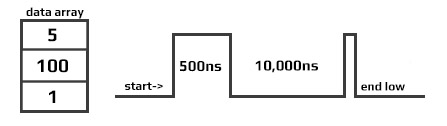
The software-based SignalGenerator (below) is more flexible but blocking. DigitalSignal.Generate is fully hardware-driven — precise, non-blocking, and uses no processor time.
Generate returns immediately — the system is free to do other work while the signal plays out in the background. When generation completes, an event fires with the final resting level of the signal:
dsig.OnGenerateFinished += (sender, endValue) => {
    if (endValue == GpioPinValue.High)
        Debug.WriteLine("Write done, end state high");
    else
        Debug.WriteLine("Write done, end state low");
};
Capture
Capture returns an array of edge timestamps. Values are in nanoseconds.
DigitalSignal is limited to the timer's max value — about 17.89 seconds. The waitForEdge flag avoids burning that budget on idle time by only starting the timer once an active pulse is detected.
using System;
using System.Diagnostics;
using System.Threading;
using GHIElectronics.TinyCLR.Devices.Gpio;
using GHIElectronics.TinyCLR.Pins;
using GHIElectronics.TinyCLR.Devices.Signals;

var digitalSignalPin = GpioController.GetDefault().OpenPin(FEZBit.Timer.DigitalSignal.Controller5.PA0);
var digitalSignal = new DigitalSignal(digitalSignalPin);

bool waitForEdge = false;   // Start capturing immediately when Capture is called.

digitalSignal.OnCaptureFinished += DigitalSignal_OnCaptureFinished;

// Capture 100 samples, timeout 15 seconds.
digitalSignal.Capture(100, GpioPinEdge.RisingEdge | GpioPinEdge.FallingEdge, waitForEdge, TimeSpan.FromSeconds(15));

// Do other work while capture runs.
Thread.Sleep(Timeout.Infinite);

void DigitalSignal_OnCaptureFinished(DigitalSignal sender, double[] buffer, uint count, GpioPinValue initialState){
    if (count == 0){
        Debug.WriteLine("No data was captured!");
        return;
    }
    for (int i = 0; i < count; i++){
        Debug.WriteLine("Sample [" + i + "]: " + buffer[i] + " ns");
    }
}
The first captured pulse may have a shorter-than-actual value due to system prep time.
ReadPulse
ReadPulse measures the total duration of a fixed number of pulses — useful for measuring frequency.
using System;
using System.Diagnostics;
using System.Threading;
using GHIElectronics.TinyCLR.Devices.Gpio;
using GHIElectronics.TinyCLR.Pins;
using GHIElectronics.TinyCLR.Devices.Signals;

var digitalSignalPin = GpioController.GetDefault().OpenPin(FEZBit.Timer.DigitalSignal.Controller5.PA0);
var digitalSignal = new DigitalSignal(digitalSignalPin);

bool waitForEdge = true;    // Wait for the first pulse before starting the timer.

digitalSignal.OnReadPulseFinished += Digital_OnReadPulseFinished;

// Time 1000 rising-edge pulses.
digitalSignal.ReadPulse(1000, GpioPinEdge.RisingEdge, waitForEdge);

Thread.Sleep(Timeout.Infinite);

void Digital_OnReadPulseFinished(DigitalSignal sender, TimeSpan duration, uint count, GpioPinValue pinValue) {
    var ticks = duration.Ticks;
    var microsecond = ((double)duration.Ticks) / 10;
    var millisecond = ((double)duration.Ticks) / 10000;
    var freq = (count / microsecond) * 1000000;

    Debug.WriteLine("GpioPinValue = " + (pinValue == GpioPinValue.High ? "High" : "Low"));
    Debug.WriteLine("PulseCount = " + count);
    Debug.WriteLine("Duration ticks = " + ticks);
    Debug.WriteLine("Duration microsecond = " + microsecond);
    Debug.WriteLine("Duration millisecond = " + millisecond);
    Debug.WriteLine("freq = " + freq / 1000.0 + " kHz");
}
Abort
Any DigitalSignal operation can be terminated early with Abort. The completion event still fires, with whatever data was collected up to the abort point.
using System;
using System.Diagnostics;
using System.Threading;
using GHIElectronics.TinyCLR.Devices.Gpio;
using GHIElectronics.TinyCLR.Pins;
using GHIElectronics.TinyCLR.Devices.Signals;

var digitalSignalPin = GpioController.GetDefault().OpenPin(FEZBit.Timer.DigitalSignal.Controller5.PA0);
var digitalSignal = new DigitalSignal(digitalSignalPin);

digitalSignal.OnReadPulseFinished += Digital_OnReadPulseFinished;

while (true) {
    if (digitalSignal.CanReadPulse) {
        digitalSignal.ReadPulse(1000, GpioPinEdge.RisingEdge, waitForEdge: false);
        Thread.Sleep(1000);
        digitalSignal.Abort();
        Debug.WriteLine("Aborted");
    }
}

void Digital_OnReadPulseFinished(DigitalSignal sender, TimeSpan duration, uint count, GpioPinValue pinValue) {
    if (count > 0) {
        var microsecond = ((double)duration.Ticks) / 10;
        var freq = (count / microsecond) * 1000000;
        Debug.WriteLine("freq = " + freq / 1000.0 + " kHz");
    }
    else {
        Debug.WriteLine("No clock found.");
    }
}
To test the code above, use PWM to generate a known pulse train. PWM and DigitalSignal share Timer resources — use different Timer controllers for the two.
Pulse Feedback
PulseFeedback measures pulse timings in three modes — built for sensor protocols that communicate by edge timing.
Echo Duration

Sends a trigger pulse on one pin, then measures how long the echo on a separate pin stays in the specified state. The trigger and echo pins must be different.
The example reads distance from an HC-SR04 ultrasonic sensor. The sensor's trigger pin is pulsed high to start a measurement, then its echo pin is held high for as long as it takes a sound pulse to bounce off the target and return.
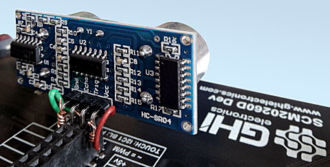
The HC-SR04 requires a 5V power supply — 3.3V logic on Trig and Echo is fine, but the module won't run from a 3.3V supply.
using System;
using System.Diagnostics;
using System.Threading;
using GHIElectronics.TinyCLR.Devices.Gpio;
using GHIElectronics.TinyCLR.Devices.Signals;
using GHIElectronics.TinyCLR.Pins;

var gpio = GpioController.GetDefault();
var distanceTriggerPin = gpio.OpenPin(FEZBit.GpioPin.P0);
var distanceEchoPin = gpio.OpenPin(FEZBit.GpioPin.P1);

var pulseFeedback = new PulseFeedback(distanceTriggerPin, distanceEchoPin, PulseFeedbackMode.EchoDuration){
    DisableInterrupts = false,
    Timeout = TimeSpan.FromSeconds(1),
    PulseLength = TimeSpan.FromTicks(100),
    EchoValue = GpioPinValue.High,
    PulseValue = GpioPinValue.High,
};

while (true){
    var time = pulseFeedback.Trigger();
    var microseconds = time.TotalMilliseconds * 1000.0;
    var distance = microseconds * 0.036 / 2.0;

    Debug.WriteLine(distance.ToString());
    Thread.Sleep(200);
}
Duration Until Echo

Similar to Echo Duration, but it measures the time between trigger and echo, not the length of the echo itself. Pulse and echo pins must be different.
The example reads distance from a Polaroid 6500 Ranging Module, which signals readiness by pulsing its ECHO pin after the host pulses INIT.
using System;
using System.Diagnostics;
using System.Threading;
using GHIElectronics.TinyCLR.Devices.Gpio;
using GHIElectronics.TinyCLR.Devices.Signals;
using GHIElectronics.TinyCLR.Pins;

var gpio = GpioController.GetDefault();
var distanceTriggerPin = gpio.OpenPin(FEZBit.GpioPin.P0);
var distanceEchoPin = gpio.OpenPin(FEZBit.GpioPin.P1);

var pulseFeedback = new PulseFeedback(distanceTriggerPin, distanceEchoPin, PulseFeedbackMode.DurationUntilEcho) {
    DisableInterrupts = false,
    Timeout = TimeSpan.FromSeconds(1),
    PulseLength = TimeSpan.FromTicks(100),
    EchoValue = GpioPinValue.High,
    PulseValue = GpioPinValue.High,
};

while (true) {
    var time = pulseFeedback.Trigger();
    var microseconds = time.TotalMilliseconds * 1000.0;
    var distance = microseconds * 0.036 / 2.0;

    Debug.WriteLine(distance.ToString());
    Thread.Sleep(1000);
}
Drain Duration

Holds the pulse pin at a specified state for a specified time, then releases it to input and measures how long the pin takes to change state. Designed for capacitive touch sensing. Only the pulse line is used — the echo pin parameter is ignored.

The example reads a capacitive touch sensor by charging a capacitor with a 10 µs pulse, then measuring the discharge time on the same pin.
using System;
using System.Diagnostics;
using System.Threading;
using GHIElectronics.TinyCLR.Devices.Gpio;
using GHIElectronics.TinyCLR.Devices.Signals;
using GHIElectronics.TinyCLR.Pins;


var gpio = GpioController.GetDefault();
var capacitiveSensePin = gpio.OpenPin(FEZBit.GpioPin.P0);

var pulseFeedback = new PulseFeedback(capacitiveSensePin, PulseFeedbackMode.DrainDuration)
{
    DisableInterrupts = false,
    Timeout = TimeSpan.FromSeconds(1),
    PulseLength = TimeSpan.FromMilliseconds(1),
    PulseValue = GpioPinValue.High,
};

while (true)
{
    Debug.WriteLine(pulseFeedback.Trigger().TotalMilliseconds.ToString());
    Thread.Sleep(1000);
}
Signal Capture
SignalCapture is a software-based digital waveform recorder. It monitors a pin and records every edge to an array — each element is the microseconds between consecutive transitions.
Read blocks until it either fills the output buffer or captures the requested number of transitions. Request only what you actually expect to capture — if the signal stops earlier, the call never returns.
The example captures the signal from pressing the LDR button on the SC20100S Dev Board. It captures up to 100 transitions or waits up to 10 seconds, with the internal pull-up enabled. Button bounces will appear as bursts of closely-spaced transitions.
using System;
using System.Diagnostics;
using System.Threading;
using GHIElectronics.TinyCLR.Devices.Gpio;
using GHIElectronics.TinyCLR.Devices.Signals;
using GHIElectronics.TinyCLR.Pins;

var gpio = GpioController.GetDefault();
var capturePin = gpio.OpenPin(FEZBit.GpioPin.P0);

var capture = new SignalCapture(capturePin);
var buffer = new TimeSpan[100];

capture.DisableInterrupts = false;
capture.Timeout = TimeSpan.FromSeconds(10);
capture.DriveMode = GpioPinDriveMode.InputPullUp;

while (true) {
    var count = capture.Read(out var init, buffer);
    Thread.Sleep(100);
}
Signal Generator
SignalGenerator is a software-based digital waveform generator. It compares an internal counter against an array of time values (in microseconds), and toggles the output pin each time the counter hits one of those values.
SignalGenerator can also produce PWM on any output pin — unlike the PwmController class, which is limited to specific Timer-backed pins. The trade-off: software PWM consumes CPU time, and more so at higher frequencies.
SignalGenerator operates in blocking mode only — while running, no processor time is yielded to other code.
The example blinks the user LED on the SC20100S Dev Board four times (one second each) every five seconds.
using System;
using System.Diagnostics;
using System.Threading;
using GHIElectronics.TinyCLR.Devices.Gpio;
using GHIElectronics.TinyCLR.Devices.Signals;
using GHIElectronics.TinyCLR.Pins;

var gpio = GpioController.GetDefault();
var signalPin = gpio.OpenPin(FEZBit.GpioPin.P0);
var signalGen = new SignalGenerator(signalPin);

var buffer = new[] {
    TimeSpan.FromSeconds(1),
    TimeSpan.FromSeconds(1),
    TimeSpan.FromSeconds(1),
    TimeSpan.FromSeconds(1),
    TimeSpan.FromSeconds(1),
    TimeSpan.FromSeconds(1),
    TimeSpan.FromSeconds(1),
    TimeSpan.FromSeconds(1),
};

signalGen.DisableInterrupts = false;
signalGen.IdleValue = GpioPinValue.Low;

while (true) {
    signalGen.Write(buffer);
    Thread.Sleep(5000);
}
API reference
| Namespace | Description |
|---|---|
| GHIElectronics.TinyCLR.Devices.Signals | Signal generator and capture classes |