Development Board
Evaluate TinyCLR with everything plugged in. SITCore Dev Boards are complete evaluation platforms — display, peripherals, click connectors, debug headers, all wired up. The fastest path from "I want to try TinyCLR" to "I'm writing production-realistic firmware on something stable."
Overview
Dev Boards are built for teams evaluating TinyCLR for a commercial product. Each board pairs a SITCore chipset or module with the surrounding hardware you'd otherwise have to build yourself — display, debug headers, peripheral connectors — so you can focus on the software from minute one.
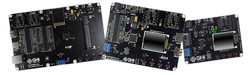
Three boards span the lineup:
- SCM20260D Dev — built around the SCM20260D SoM. Cortex-M7 at 480 MHz, 4.3″ capacitive touch display, Ethernet, camera connector. The full-featured eval platform.
- SC20100S Dev — built around the SC20100S SoC. Cortex-M7 at 480 MHz, 1.8″ display, dual mikroBUS, SD card slot.
- SC13048Q Dev — built around the SC13048Q SoC. Cortex-M4 at 80 MHz, 1.8″ display, single mikroBUS. The compact, low-power option.
Board comparison
| Spec | SCM20260D Dev | SC20100S Dev | SC13048Q Dev |
|---|---|---|---|
| Chipset / module | SCM20260D SoM | SC20100S SoC | SC13048Q SoC |
| Speed | 480 MHz | 480 MHz | 80 MHz |
| Display | 4.3″ 480×272 cap. touch (7″ optional) | 1.8″ 160×128 | 1.8″ 160×128 |
| mikroBUS slots | 2 | 2 | 1 |
| USB client | ✓ | ✓ | ✓ |
| USB host | ✓ | ✓ | — |
| SD card slot | ✓ | ✓ | — |
| Camera connector | ✓ | — | — |
| Ethernet connector | ✓ | — | — |
| CAN transceiver | ✓ | ✓ | ✓ |
| Buzzer | ✓ | ✓ | ✓ |
| Supercap RTC backup | ✓ | ✓ | ✓ |
| Barrel power jack | ✓ | ✓ | ✓ |
| HDMI option | ✓ (via adaptor) | — | — |
Getting started
Dev Boards ship ready to run TinyCLR — plug in and code.
- Connect the board's USB client port to your PC with a USB-C cable.
- Install Visual Studio (Community Edition works) and the TinyCLR tooling.
- Update the board's firmware if needed.
- Deploy your first application from Visual Studio.
For the SCM20260D Dev, install the SCM20260D SoM into the SO-DIMM socket and plug in the display ribbon cable before powering up.
See Getting Started for the full walkthrough.
Powering the boards
All three Dev Boards can be powered through either the USB client connector or the barrel jack.
Always use the barrel jack when a display is connected. USB does not provide sufficient current for the display backlight — especially with the 4.3″ and 7″ panels on the SCM20260D Dev.
Barrel jacks accept a 5.5 × 2.1 mm power plug — pin positive, sleeve negative. Boards accept a wide voltage range but use linear regulators that run hotter with higher input voltages. Recommended input: 6–12 V. For high-current projects, use a lower voltage to keep the regulator cooler.
SCM20260D Dev Board
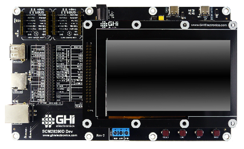
The SCM20260D Dev Board is built around the SCM20260D SoM — Cortex-M7 at 480 MHz, 32 MB external SDRAM, 16 MB external flash, on-board Ethernet PHY. The board pairs the module with a 4.3″ capacitive touch display, two 40-pin peripheral header rows, two mikroBUS slots, Ethernet, CAN, USB host and client, an SD card slot, a parallel camera interface (DCMI), supercap RTC backup, a buzzer, user LEDs, a reset button, and user-programmable boot buttons.
Install the module into the SO-DIMM socket, plug in the display (if used), and connect USB to start coding.
SCM20260D Dev Board Schematic · SCM20260D Dev Board 3D STEP File
Display options
The SCM20260D Dev exposes a header with all parallel display signals plus I²C and GPIO for capacitive touch. Two display options ship from GHI Electronics, plus an HDMI adaptor.
UD435 — 4.3″ capacitive touch
Ships included with the SCM20260D Dev Board. 4.3″ 480×272 TFT with capacitive touch — uses I²C1 for touch and PJ14 for the touch interrupt. Backlight is controllable through PA15.
- Display module: ER-TFT043-3
- Touch panel: ER-TPC043-2
- 4.3″ Display Module Schematic
See the TinyCLR Samples repo for usage examples, and the Graphics and Display feature pages for deeper documentation.
Display configuration values:
| Property | Value |
|---|---|
| Width | 480 |
| Height | 272 |
| DataFormat | RGB56 |
| Pixel Clock Rate | 8_000_000 <= x <= 24_000_000 Hz |
| Pixel Polarity | low |
| DataEnable Is Fixed | false |
| DataEnable Polarity | low |
| Horizontal Back Porch | 46 |
| Horizontal Front Porch | 16 |
| Horizontal Sync Polarity | low |
| Horizontal Sync Pulse Width | 1 |
| Vertical Back Porch | 23 |
| Vertical Front Porch | 7 |
| Vertical Sync Polarity | low |
| Vertical Sync Pulse Width | 1 |
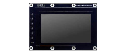
UD700 — 7″ capacitive touch
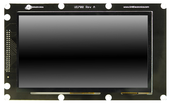
Special order option — contact us to order. 7″ 800×480 TFT with capacitive touch — same touch and backlight pins as UD435.
- Display module: ER-TFT070A2-4
- Touch panel: ER-TPC07-4
- 7″ Display Module Schematic
Display configuration values:
| Property | Value |
|---|---|
| Width | 800 |
| Height | 480 |
| DataFormat | RGB565 |
| Pixel Clock Rate | 8_000_000 <= x <= 24_000_000 Hz |
| Pixel Polarity | false |
| DataEnable Is Fixed | false |
| DataEnable Polarity | low |
| Horizontal Back Porch | 46 |
| Horizontal Front Porch | 16 |
| Horizontal Sync Polarity | false |
| Horizontal Sync Pulse Width | 1 |
| Vertical Back Porch | 23 |
| Vertical Front Porch | 7 |
| Vertical Sync Polarity | false |
| Vertical Sync Pulse Width | 1 |
HDMI adaptor
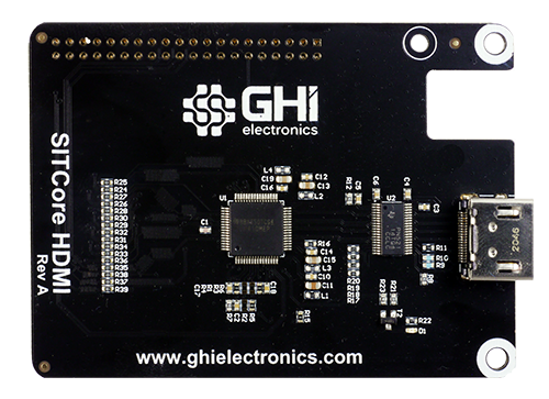
Optional adaptor that replaces the display with an HDMI output. Built around TI's TFP410 HDMI transmitter. A NuGet driver library handles the configuration internally:
var hdmi = new TFP410Controller(i2cController, Resolution.HD720p, DisplayOrientation.Degrees0, resetPin);
displayController.SetConfiguration(hdmi.Configuration);
SITCore HDMI Adaptor Schematic
Camera options
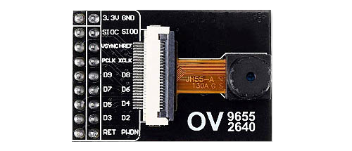
The SC20260 chip and the SCM20260 modules include a parallel Digital Camera Interface (DCMI). The SCM20260D Dev exposes the camera signals on a dedicated header. The pinout matches the popular OV9655 breakout board, available from multiple sources.
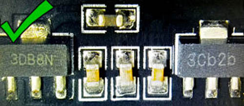
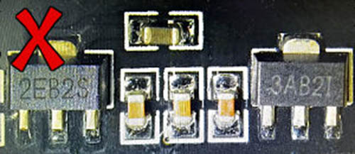
Some OV9655 breakout boards ship with voltage regulators that don't work reliably. We've seen the boards labeled "3DB8N" and "3Cb2b" work well, while boards labeled "2EB2S" and "3AB2I" do not. These are our observations only — we can't guarantee the functionality of any third-party product.
Working module (regulators labeled "3DB8N" and "3Cb2b"):
Non-working module (regulators labeled "2EB2S" and "3AB2I"):
Demo program
The SCM20260D Dev Board ships with a demonstration program. Find it in the TinyCLR-Samples repo.
SC20100S Dev Board
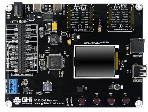
The SC20100S Dev Board is built around the SC20100S SoC — Cortex-M7 at 480 MHz. The board includes a 1.8″ color SPI display, two 40-pin peripheral header rows, two mikroBUS slots, a CAN transceiver, USB host and client, supercap RTC backup, an SD card slot, a buzzer, user LEDs, a reset button, and user-programmable boot buttons.
SC20100S Dev Board Schematic · SC20100S Dev Board 3D STEP File
SC13048Q Dev Board
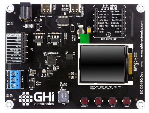
The SC13048Q Dev Board is built around the SC13048Q SoC — Cortex-M4 at 80 MHz. The board includes a 1.8″ color SPI display, a 10-pin peripheral header row, one mikroBUS slot, a CAN transceiver, USB client, supercap RTC backup, a buzzer, user LEDs, a reset button, and user-programmable boot buttons.
SC13048Q Dev Board Schematic · SC13048Q Dev Board 3D STEP File
USB-C connector
All SITCore Dev Boards use USB-C for application deployment and debugging. Every USB-A to USB-C cable we've tested works as expected. USB-C to USB-C cables can give inconsistent results, and most USB-C hubs do not work when using USB-C to USB-C cables.
If you have trouble deploying or debugging, connect the board directly to your computer with a USB-A to USB-C cable.
Ordering
| Part number | Description | MSRP |
|---|---|---|
| SCD-20260D-C | SCM20260D Dev Board | $199.95 |
| SCD-20100S-C | SC20100S Dev Board | $99.95 |
| SCD-13048Q-B | SC13048Q Dev Board | $59.95 |
| SCD-HDMI-A | SITCore HDMI Adapter | Special order — contact us |
| UCD-D70-A | 7″ Capacitive Touch Display | Special order — contact us |
All SITCore Dev Boards are available through our global distributors.
See also
- System on Chip — the SC13048Q and SC20100S chipsets that the smaller Dev Boards are built on. Covers startup, firmware loading, and lower-level design reference.
- System on Module — the SCM20260D module that powers the flagship Dev Board.
- Single Board Computer — already-assembled boards in maker form factors. Better than a Dev Board when prototyping in a maker ecosystem (Arduino, Pico, Feather, micro:bit).
- Experimenter Kit — structured learning kit built around the FEZ Bit, paired with a companion eBook. Built for teaching .NET on embedded.