Displays
Endpoint supports two display categories:
- Parallel TFT: a panel wired directly to the board's parallel RGB controller. Fastest option; refresh runs off the hardware without any CPU work.
- Serial (SPI / I2C) displays and character displays: any panel you can drive from a bus. The next sections cover both.
For panels with a touchscreen, see Touch Screen.
The parallel display is driven through
GHIElectronics.Endpoint.Devices.Display. Panel timings and backlight pin
live in /config/display.json, so they are set once and the application
simply opens, enables and flushes.
Parallel display
One-time configuration
Write the panel's timings and backlight pin to the config partition. You only have to do this once per board (settings persist across reboots).
- .NET
- Python
- C/C++
using GHIElectronics.Endpoint.Core;
using GHIElectronics.Endpoint.Devices.Display;

var settings = new DisplaySettings {
    Type = DisplayType.Parallel,
    EnableAtBoot = false,                     // true = board brings the panel up during boot
    Logo = null,                              // 24-bit BMP filename on /config, or null
    Backlight = new BacklightSettings {
        Pin = EPDomino24.Backlight,           // or -1 to leave the backlight alone
        ActivePolarity = SignalPolarity.ActiveHigh,
    },
    Parallel = new ParallelLcdSettings {
        Width        = 480, Height = 272,
        PixelClockHz = 10_000_000,
        HFrontPorch  = 2, HBackPorch = 2, HSync = 41,
        VFrontPorch  = 2, VBackPorch = 2, VSync = 10,
        BitsPerPixel = 16,                    // 16 = RGB565, 24 = RGB888
    },
};
DisplayController.SetSettings(settings);
from GHIElectronics.Endpoint.Core import EPDomino24
from GHIElectronics.Endpoint.Devices.Display import (
    BacklightSettings, DisplayController, DisplaySettings, DisplayType,
    ParallelLcdSettings, SignalPolarity)

settings = DisplaySettings()
settings.Type = DisplayType.Parallel
settings.EnableAtBoot = False                 # True = board brings the panel up during boot
settings.Logo = None                          # 24-bit BMP filename on /config, or None

settings.Backlight = BacklightSettings()
settings.Backlight.Pin = EPDomino24.Backlight # or -1 to leave the backlight alone
settings.Backlight.ActivePolarity = SignalPolarity.ActiveHigh

settings.Parallel = ParallelLcdSettings()
settings.Parallel.Width,        settings.Parallel.Height       = 480, 272
settings.Parallel.PixelClockHz = 10_000_000
settings.Parallel.HFrontPorch,  settings.Parallel.HBackPorch, settings.Parallel.HSync = 2, 2, 41
settings.Parallel.VFrontPorch,  settings.Parallel.VBackPorch, settings.Parallel.VSync = 2, 2, 10
settings.Parallel.BitsPerPixel = 16           # 16 = RGB565, 24 = RGB888

DisplayController.SetSettings(settings)
#include <endpoint/Display.h>
#include <endpoint/EPDomino24.h>

using namespace GHIElectronics::Endpoint::Core;
using namespace GHIElectronics::Endpoint::Devices::Display;

DisplaySettings settings;
settings.Type = DisplayType::Parallel;
settings.EnableAtBoot = false;                // true = board brings the panel up during boot
settings.Logo = "";                           // 24-bit BMP filename on /config, or empty

BacklightSettings backlight;
backlight.Pin = EPDomino24::Backlight;        // or -1 to leave the backlight alone
backlight.ActivePolarity = SignalPolarity::ActiveHigh;
settings.Backlight = backlight;

ParallelLcdSettings parallel;
parallel.Width        = 480; parallel.Height = 272;
parallel.PixelClockHz = 10'000'000;
parallel.HFrontPorch  = 2; parallel.HBackPorch = 2; parallel.HSync = 41;
parallel.VFrontPorch  = 2; parallel.VBackPorch = 2; parallel.VSync = 10;
parallel.BitsPerPixel = 16;                   // 16 = RGB565, 24 = RGB888
settings.Parallel = parallel;

DisplayController::SetSettings(settings);
Enable and show pixels
Once configured, open the controller, enable it, and push a frame. The pixels can come from any .NET graphics library (see Graphics) or from your own code.
- .NET
- Python
- C/C++
using var display = DisplayController.GetDefault();   // null if Type is None
if (display == null) return;

display.Enable();

// Pixel buffer in RGB565 (width * height * 2 bytes)
var pixels = new byte[display.Width * display.Height * 2];
// ... fill the buffer ...

display.Flush(pixels);                                 // defaults to Rgb565
from GHIElectronics.Endpoint.Devices.Display import DisplayController

display = DisplayController.GetDefault()      # None if Type is None
if display is None:
    exit()

with display:
    display.Enable()

    # Pixel buffer in RGB565 (width * height * 2 bytes)
    pixels = bytearray(display.Width * display.Height * 2)
    # ... fill the buffer ...

    display.Flush(pixels)                     # defaults to Rgb565
#include <vector>
#include <endpoint/Display.h>

using namespace GHIElectronics::Endpoint::Devices::Display;

auto display = DisplayController::GetDefault();   // nullptr if Type is None
if (!display) return 0;

display->Enable();

// Pixel buffer in RGB565 (width * height * 2 bytes)
std::vector<uint8_t> pixels(display->Width() * display->Height() * 2);
// ... fill the buffer ...

display->Flush(pixels.data(), pixels.size());     // defaults to Rgb565
For other pixel formats, pass one explicitly:
- .NET
- Python
- C/C++
using System.Drawing.Imaging;
display.Flush(rgb888Pixels, PixelFormat.Format24bppRgb);
display.Flush(argb32Pixels, PixelFormat.Format32bppArgb);
from GHIElectronics.Endpoint.Devices.Display import PixelFormat

display.Flush(rgb888_pixels, PixelFormat.Format24bppRgb)
display.Flush(argb32_pixels, PixelFormat.Format32bppArgb)
display->Flush(rgb888Pixels.data(), rgb888Pixels.size(), PixelFormat::Format24bppRgb);
display->Flush(argb32Pixels.data(), argb32Pixels.size(), PixelFormat::Format32bppArgb);
A partial update is also supported:
- .NET
- Python
- C/C++
display.Flush(regionPixels, PixelFormat.Format16bppRgb565,
              x: 100, y: 50, width: 200, height: 100);
display.Flush(region_pixels, PixelFormat.Format16bppRgb565,
              x=100, y=50, width=200, height=100)
display->Flush(regionPixels.data(), regionPixels.size(),
               PixelFormat::Format16bppRgb565,
               /*x*/ 100, /*y*/ 50, /*width*/ 200, /*height*/ 100);
Python does not support method overloading, so the binding exposes a single
Flush(pixels, format=PixelFormat.Format16bppRgb565, x=0, y=0, width=None, height=None);
the three call sites above supply different trailing arguments to that one method.
Boot logo
Set DisplaySettings.Logo to the filename of a 24-bit BMP on the config
partition and call ShowLogo() right after Enable() to paint it:
- .NET
- Python
- C/C++
display.Enable();
display.ShowLogo();     // reads /config/<logo-filename>.bmp and flushes it
display.Enable()
display.ShowLogo()      # reads /config/<logo-filename>.bmp and flushes it
display->Enable();
display->ShowLogo();    // reads /config/<logo-filename>.bmp and flushes it
If EnableAtBoot is also true, the board does this itself during boot, so
the user's program sees the panel already lit with the logo.
Serial (SPI / I2C) displays
SPI and I2C panels (and any other non-parallel panel such as UART or an
HDMI bridge) are driven by their own DisplayController subclass. The
abstract contract is small:
Enable: run the panel's power-up / init sequenceDisable: power it downFlush: push pixelsWidth/Height/IsEnabled: visible panel size and state
Application code uses the same Enable / Flush pattern as the built-in
parallel panel, so a graphics stack written against DisplayController works
against either. GetDefault() only returns the parallel panel; a serial
driver is constructed directly.
Using a ready-made driver
GHI Electronics publishes a driver for the HiLetgo ILI9341 240x320 SPI TFT in all three languages. Source on GitHub:
- .NET:
GHIElectronics.Endpoint.Drivers.HiLetgo.ILI9341(NuGet package) - Python:
ili9341.py(drop the file into the project) - C/C++:
Ili9341.h(header-only, drop the file into the project)
All three use the same Initialize + Flush pattern.
- .NET
- Python
- C/C++
using System.Device.Gpio;
using System.Device.Spi;
using GHIElectronics.Endpoint.Core;
using GHIElectronics.Endpoint.Drivers.HiLetgo.ILI9341;

using var gpio = new GpioController(new EPDomino24.Gpio.Driver());
using var spi  = SpiDevice.Create(ILI9341Controller.GetConnectionSettings(EPDomino24.Spi.Spi1));

using var tft = new ILI9341Controller(
    spi:   spi,
    cs:    EPDomino24.Gpio.Pin.PA14,
    dc:    EPDomino24.Gpio.Pin.PA10,
    reset: EPDomino24.Gpio.Pin.PF4,
    gpio:  gpio);
tft.SwapRedBlue = true;        // set for modules where yellow shows as cyan
tft.Enable();

// Pixel buffer in RGB565 (width * height * 2 bytes)
var pixels = new byte[tft.Width * tft.Height * 2];
// ... fill the buffer ...
tft.Flush(pixels);
from GHIElectronics.Endpoint.Core import EPDomino24, SpiController
from GHIElectronics.Endpoint.Devices.Spi import SpiDevice, SpiConnectionSettings, SpiMode
from GHIElectronics.Endpoint.Devices.Gpio import GpioController

from ili9341 import Ili9341        # see driver section below

SpiController.Initialize(EPDomino24.Spi.Spi1, bufferSize=4096)
settings = SpiConnectionSettings(EPDomino24.Spi.Spi1)
settings.Mode = SpiMode.Mode0
settings.ClockFrequency = 10_000_000
spi = SpiDevice.Create(settings)

gpio = GpioController()
tft = Ili9341(gpio, spi,
              cs_pin=EPDomino24.Gpio.Pin.PA14,
              dc_pin=EPDomino24.Gpio.Pin.PA10,
              rst_pin=EPDomino24.Gpio.Pin.PF4,
              swap_red_blue=True)   # set for modules where yellow shows as cyan
tft.initialize()

# Pixel buffer in RGB565 (width * height * 2 bytes)
pixels = bytes(tft.width * tft.height * 2)
# ... fill the buffer ...
tft.flush(pixels)
#include <endpoint.h>
#include <endpoint/SpiController.h>
#include "Ili9341.h"                // see driver section below

namespace Core = GHIElectronics::Endpoint::Core;
namespace Gpio = GHIElectronics::Endpoint::Devices::Gpio;
namespace Spi  = GHIElectronics::Endpoint::Devices::Spi;

Core::SpiController::Initialize(Core::EPDomino24::Spi::Spi1, /*bufferSize*/ 4096);
Spi::SpiConnectionSettings settings(Core::EPDomino24::Spi::Spi1);
settings.Mode = Spi::SpiMode::Mode0;
settings.ClockFrequency = 10'000'000;
auto spi = Spi::SpiDevice::Create(settings);

Gpio::GpioController gpio;
Ili9341 tft(gpio, spi,
            /*cs*/  Core::EPDomino24::Gpio::Pin::PA14,
            /*dc*/  Core::EPDomino24::Gpio::Pin::PA10,
            /*rst*/ Core::EPDomino24::Gpio::Pin::PF4);
tft.SwapRedBlue(true);              // set for modules where yellow shows as cyan
tft.Initialize();

// Pixel buffer in RGB565 (width * height * 2 bytes)
std::vector<uint8_t> pixels(tft.Width() * tft.Height() * 2);
// ... fill the buffer ...
tft.Flush(pixels);
:::note Wiring gotchas (worth knowing even with the driver)
- Chip select is driven by a GPIO, not by the SPI controller's hardware NSS.
The driver opens the pin you pass and toggles it around each transaction.
On .NET,
SpiConnectionSettingsneedschipSelectLine: 0explicitly; Microsoft's Linux SPI stack does not accept-1. - Data / Command pin: ILI9341 distinguishes commands from pixel data by a separate GPIO (D/C). Low = command byte, high = data byte.
- Reset pin: an active-low pulse brings the chip out of reset reliably at startup. Tie to 3.3 V or leave unwired only if your module has an on-board reset circuit.
- Pixel format on the wire is 16 bpp big-endian, but Canvas
writes RGB565 little-endian (ready for
/dev/fb0). The driver byte-swaps each pixel inFlush; you never see the raw bytes. - Red / Blue swap: some HiLetgo and eBay modules have the physical
color filter wired as BGR regardless of what the chip's MADCTL bit
says, so yellow renders as cyan and red as blue. Set
SwapRedBlue = truefor those modules. - Backlight on most 2.2"–2.8" ILI9341 modules has a current-limit resistor on board; tie LED to +3.3 V for always-on, or drive from a PWM pin if you want to dim it. :::
Writing your own driver
To support a panel we do not ship a driver for, subclass DisplayController
and drive the hardware through the standard SPI / I2C / GPIO APIs. The
skeleton is small:
- .NET
- Python
- C/C++
using System;
using System.Device.Gpio;
using System.Device.Spi;
using GHIElectronics.Endpoint.Devices.Display;
using PixelFormat = System.Drawing.Imaging.PixelFormat;

public sealed class MyPanelController : DisplayController {
    private readonly SpiDevice spi;
    private readonly GpioController gpio;
    private readonly int dcPin, resetPin;
    private bool enabled;

    public MyPanelController(SpiDevice spi, int dc, int reset, GpioController gpio) {
        this.spi = spi;
        this.gpio = gpio;
        this.dcPin = dc;
        this.resetPin = reset;
        this.gpio.OpenPin(dc, PinMode.Output);
        this.gpio.OpenPin(reset, PinMode.Output);
    }

    public override int  Width     => 240;
    public override int  Height    => 320;
    public override bool IsEnabled => this.enabled;

    public override void Enable() {
        // reset pulse + vendor init sequence over SPI ...
        this.enabled = true;
    }

    public override void Disable() {
        // put the panel to sleep
        this.enabled = false;
    }

    public override void Flush(ReadOnlySpan<byte> pixels, PixelFormat format,
                               int x, int y, int width, int height) {
        // 1) set the panel's draw window to (x, y, width, height)
        // 2) send pixels over SPI in the panel's native format
    }

    public override void Dispose() {
        try { this.Disable(); } catch { }
        this.gpio.ClosePin(this.dcPin);
        this.gpio.ClosePin(this.resetPin);
        this.spi.Dispose();
    }
}
from GHIElectronics.Endpoint.Devices.Gpio import GpioController, PinMode
from GHIElectronics.Endpoint.Devices.Display import DisplayController, PixelFormat

class MyPanelController(DisplayController):
    def __init__(self, spi, dc, reset, gpio):
        self._spi = spi
        self._gpio = gpio
        self._dc_pin = dc
        self._reset_pin = reset
        self._enabled = False
        gpio.OpenPin(dc, PinMode.Output)
        gpio.OpenPin(reset, PinMode.Output)

    @property
    def Width(self): return 240

    @property
    def Height(self): return 320

    @property
    def IsEnabled(self): return self._enabled

    def Enable(self):
        # reset pulse + vendor init sequence over SPI ...
        self._enabled = True

    def Disable(self):
        # put the panel to sleep
        self._enabled = False

    def _Flush(self, pixels, format_, x, y, width, height):
        # 1) set the panel's draw window to (x, y, width, height)
        # 2) send pixels over SPI in the panel's native format
        pass

    def Dispose(self):
        try:
            self.Disable()
        except Exception:
            pass
        self._gpio.ClosePin(self._dc_pin)
        self._gpio.ClosePin(self._reset_pin)
        self._spi.Dispose()
#include <cstdint>
#include <endpoint/Display.h>
#include <endpoint/Gpio.h>
#include <endpoint/Spi.h>

using namespace GHIElectronics::Endpoint::Devices::Display;
using namespace GHIElectronics::Endpoint::Devices::Gpio;
using namespace GHIElectronics::Endpoint::Devices::Spi;

class MyPanelController : public DisplayController {
public:
    MyPanelController(SpiDevice spi, int dc, int reset, GpioController& gpio)
        : spi_(std::move(spi)), gpio_(gpio), dcPin_(dc), resetPin_(reset) {
        gpio.OpenPin(dc, PinMode::Output);
        gpio.OpenPin(reset, PinMode::Output);
    }

    int  Width()     const override { return 240; }
    int  Height()    const override { return 320; }
    bool IsEnabled() const override { return enabled_; }

    void Enable() override {
        // reset pulse + vendor init sequence over SPI ...
        enabled_ = true;
    }

    void Disable() override {
        // put the panel to sleep
        enabled_ = false;
    }

    using DisplayController::Flush;
    void Flush(const uint8_t* /*pixels*/, size_t /*length*/, PixelFormat /*format*/,
               int /*x*/, int /*y*/, int /*width*/, int /*height*/) override {
        // 1) set the panel's draw window to (x, y, width, height)
        // 2) send pixels over SPI in the panel's native format
    }

    ~MyPanelController() override {
        try { Disable(); } catch (...) {}
        gpio_.ClosePin(dcPin_);
        gpio_.ClosePin(resetPin_);
        spi_.Dispose();
    }

private:
    SpiDevice      spi_;
    GpioController& gpio_;
    int            dcPin_;
    int            resetPin_;
    bool           enabled_ = false;
};
The open-source ILI9341 driver source is a complete working example of this pattern.
Character displays
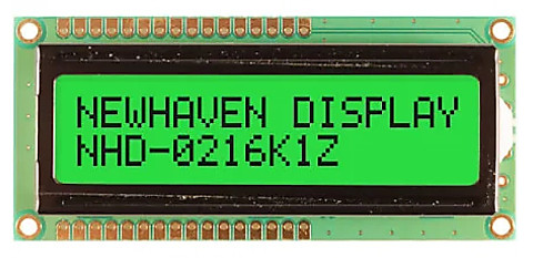
Character-matrix LCDs (2x16, 4x20, etc.) use the standard Iot.Device.CharacterLcd library from .NET IoT. Wire the panel to any GPIO/I2C/SPI pins and drive it with the same code you would use on any .NET IoT board.